
Notifications
Clear all
Computers & IT
143
Posts
55
Users
28
Reactions
24.3 K
Views

@hiddenvector well, it's not the most helpful experience but I accidentally picked up an MSI GL63-8RD, from the previous gen, i7-8750H, 1050ti 4gb. I think it doesn't have usb-c output capabilities (at least I got no reaction), but it's happy outputting everything on HDMI.
My main project I'm still waiting on will be a board from an Alienware M15, i7-8750H as well but the 2080 max-q with it. While researching I saw people talk about unlocking bios settings (for undervolting generally) but some of the settings were also a choice of primary display output. So bios modding might be a solution? But you might need a compatible EDP screen to get there if so. And it seems a bit unpleasant to rely on a bios setting sticking like that.
Another option might be the EDP to DP adapter path, I linked something on a previous page, and it seems like a nice idea to make that output work. But on further research I think that's a very complex thing to do, EDP connectors are not standard, so you'd have to find your pinout and probably adapt it. I did see someone make an EDP to EDP adapter recently in a different context, here, might be some inspiration. But I really hope I won't have to do this, seems painful.
This post was modified 2 months ago 2 times by lucilletea
Posted : 05/08/2026 7:05 am
HiddenVector reacted

@civilizayden if the cpu and gpu die isn't the same height you can add a thin piece of copper to the die which is lower to bring them on the same level. is there any recycle center in your place? you might find pretty good deals there.
Posted : 05/08/2026 8:23 am
@hiddenvector try to reseat the ram, and clear CMOS.
Posted : 05/08/2026 8:28 am
HiddenVector reacted
found pretty good deals :
https://www.ebay.com/itm/167058959160
https://www.ebay.com/itm/306697042290
https://www.ebay.com/itm/256621493516
https://www.ebay.com/itm/168556686486
https://www.ebay.com/itm/336572124931
https://www.ebay.com/itm/298271948454
https://www.ebay.com/itm/306761323723
https://www.ebay.com/itm/227453321496
This post was modified 2 months ago by Muzammil17
Posted : 05/08/2026 8:48 am

Hi @diyperks!
I saw the video the day it came out and actually picked up a board just this week. It's the also an HP Omen one like the one in your video! I did run into the problem of it's heatsink not being available on the market anywhere! So I had been researching possible copper heatsinks that I would diy myself. My only question right now, is can you tell me what the heatsinks are that you used for this board in your video? Thanks for all your videos that continue to inspire and I am looking forward to you next project!
-curious diy-er
This post was modified 2 months ago by Mideval135
Posted : 06/08/2026 10:05 pm

Can you give us more information on the pcb pillars please? You seem to drill straight through the aluminium so I suppose the pillars are secured on the reverse side with some kind of bolt? What size pillars did you use for your laptop? My salvaged ultra book seems to use m2.
Posted : 08/08/2026 2:06 pm

I have found an FX505G that has a broken screen, after removing internal nvme drive I managed to to a live linux usb to boot and running. Tried disconnecting screen to see if bios would appear on external monitor but so far no luck. Unable to change boot order I will have to use a usb drive to boot system on either the nvme drive or a ssd sata drive I have put in for now.
My question is can I reach bios on the ASUS FX505G on an external monitor if so how?
Posted : 10/08/2026 1:47 pm
@mrgreen disconnect the display cable and close the lid, and connect external display and try again, maybe the lid close sensor still thinks that the internal display is still connected.
Posted : 11/08/2026 5:46 am
@mrgreen you can change the boot order, every laptop and pc allows that, is secure boot disabled? you have to use the arrow keys or pgUp or pgDn keys, the BIOS shows how to change the boot order on the right side, like a info tab.
Posted : 11/08/2026 5:49 am
I will give closing lid a try. So far I have been unable to reach bios. Have managed to get Linux booted and running on an external display.
Thanks
MrG
Posted : 11/08/2026 1:01 pm

found pretty good deals :
https://www.ebay.com/itm/167058959160
https://www.ebay.com/itm/306697042290
https://www.ebay.com/itm/256621493516
https://www.ebay.com/itm/168556686486
https://www.ebay.com/itm/336572124931
https://www.ebay.com/itm/298271948454
Those are pretty good deals, though #2 and #8 are both non-functional boards. #7 would be an amazing board for a PC build, but it's bloody expensive. I could buy a single stick of DDR5 RAM for that much 😁
My worktable is a site of frequent detonations. Please knock so I don't start a Lithium fire when you startle me.
Posted : 11/08/2026 10:50 pm
marcdraco reacted

Hey great video. What size copper wire did you use?
Posted : 11/08/2026 11:24 pm

For a monitor could I not just use a USBC-HDMI and connect it to my TV? I know it defeats the whole build but if I source a good board, and power it with good additional ports too, and use my TV as the monitor and speakers I would most likely be able to source a much more powerful board (saving money from the other ancillaries)
I was then thinking to pair this with the DIY surround sound system video that you posted
Posted : 18/08/2026 12:04 am

Hello everyone! Long time watcher first time commenter!
Love your stuff.
This is the first video I’ve ever thought, “I’ll have a go at that!”
So I already have a gutted 27” iMac with a screen in perfect condition. I converted it to an external monitor using the same display board you used and even got the speakers working.
You inspired me to try to fit a laptop motherboard inside the chassis and make it an all in one again.
I have an old
Dell Latitude 3420 with Intel i5-1135G7 16GB & RAM and 256GB NVME.
Any advice before I create my Frankenmac?
This post was modified 2 months ago by Sterntooth
Posted : 19/08/2026 10:47 pm
@sterntooth I've built some stuff like this before, and while I haven't finished most of the builds, what I have learned is that it's really annoying to fit different motherboards inside an iMac frame. If I were you and I had the resources (sheet plastic or metal, acrylic, 3D printer, or access to other sheet material) I wouldn't even bother trying to reuse the iMac body; I would build a whole new custom case. LCD panels and motherboards are pretty easy to pair up--attach the motherboard to the back of the panel with some stand-offs, and build a case around it--the trouble comes when trying to attach the thing to some kind of monitor mount, whether bought or custom. One way you might do it is use a strong glue to attach a sheet of material, 1/4" plastic perhaps, to the back of the panel to have something rigid and thick to screw into, then go from there.
If you do find a way to house the motherboard inside the iMac frame with all the ports accessible, I'd love to see some pictures, as I haven't managed a feat like that yet 😆
My worktable is a site of frequent detonations. Please knock so I don't start a Lithium fire when you startle me.
Posted : 20/08/2026 1:57 pm
We shall see what transpires. It will probably end up a mess of hot glue and tears!
I really like the idea of reusing the iMac shell as it’s a work of art and a shame to throw it away.
i don’t have a 3D printer but maybe it’s something I’ll look at in the future.
I don’t really need the ports to be accessible. I have a USB C hub which I will just mount to the back of the chassis.
hopefully I can do similar to this video and power everything from one brick directly from the existing power in and hopefully connect the power button to the existing one too!
it’s not really going to be for daily use, I just want to see if I can do it!
This post was modified 2 months ago by Sterntooth
Posted : 20/08/2026 2:10 pm

It will probably end up a mess of hot glue and tears!
Could be worse, could be hot lead, smoking ics and another month's shopping down the pan. 🙂
Take everything I say with a pinch of salt, I might be wrong and it's a very *expensive* way to learn!
Posted : 21/08/2026 2:08 pm
@sterntooth Definitely give it a go if you want to. I agree that iMac cases look cool, and if you have a USB-C hub that definitely makes it easier. And yeah, it doesn't have to be for daily use to justify building it--if I thought like that, I would have about 6 fewer PCs, and I would be sadder.
This post was modified 2 months ago by Imp Inventor
My worktable is a site of frequent detonations. Please knock so I don't start a Lithium fire when you startle me.
Posted : 21/08/2026 10:08 pm
marcdraco reacted
I made one of mine into a monitor then had to give it up due to lack of space. (Don't ask.)
But yeah, I agree with the @imp_inventor, go for it; what have you got to lose?
Take everything I say with a pinch of salt, I might be wrong and it's a very *expensive* way to learn!
Posted : 22/08/2026 3:09 am

Came back to this project after some time. Didn't have much free time and was getting a bit frustrated 😅.
@Muzammil17, thanks for the suggestions! I reset CMOS multiple times and resat (reseated?) the two 8gb RAM sticks I have in every configuration (single, dual, in each slot). Still no dice.
@lucilletea, also thank you for the reply! Unfortunately, neither usb-c or HDMI are giving me anything.
@basvos, this actually helped a bit I think. Putting in m.2 with win11 pre installed gave me different results. No images on the screen but the drive's LED lit up and the GPU fans kicked on after what seemed like a few seconds of the OS booting.
So my guess is the motherboard is running but still not displaying anything to an external monitor. Maybe I need to make it think the lid is closed? Still trying to look into that, I'm not finding much documentation on the motherboard of this model.
Posted : 24/08/2026 3:02 am
-
-
Since your board has reset its CMOS, use this exact sequence to bypass the CMOS warning screen and get a video signal out:Step 1: Clear the CMOS Prompt Blindly
- Remove your NVMe drive entirely (this stops the board from trying to boot a broken OS loop).
- Connect your monitor to the HDMI port.
- Turn on the motherboard and wait 60 seconds for the memory to train.
- Press the F2 key once on an external USB keyboard. (This commands the motherboard to accept default time/date settings and bypass the hidden CMOS error screen).
- Wait 10 seconds. The motherboard should now automatically drop into the standard BIOS or an EFI shell.
Step 2: Wake Up the Video Ports (The Right Side USB-C)On the MSI GS75 9SG, the standard HDMI port is routed through the integrated Intel graphics, which is currently failing its internal loop check. However, the Thunderbolt 3 USB-C port (located on the right side of the board) is hardwired directly to the NVIDIA RTX GPU.- If the HDMI port remains black after Step 1, unplug it.
- Use a USB-C to DisplayPort cable (or USB-C to HDMI adapter) and plug it into the Right-Side USB-C port.
- Turn the board on. The dedicated GPU will often force a broadcast signal out of its native hardware lanes even if the internal screen is missing.
Do you have an external USB mouse or keyboard with LEDs plugged in? If you turn the board on, do those LED lights stay lit, or do they flash once and turn off? Knowing this will confirm if the motherboard is actually loading code.
-
This post was modified 1 month ago 4 times by Muzammil17
Posted : 25/08/2026 4:21 am
marcdraco reacted
@hiddenvector even my ASUS TUF a15 might have the same problem, so having the internal display even if it is broken is required, to change the BIOS settings to use external display, if the CMOS battery is removed all the setting are defaulted. thankfully the display is available from the seller i purchased the motherboard for 35$.
EDIT: the only solution i found that i have to use the "thunderbolt 3/4 to HDMI cable", the thunderbolt port is directly connected to the CPU, so it should work, there are some type c port that are normal, they cannot output display out, so check all the ports to see if you get a display out when you are in BIOS.
This post was modified 1 month ago by Muzammil17
Posted : 25/08/2026 10:45 am
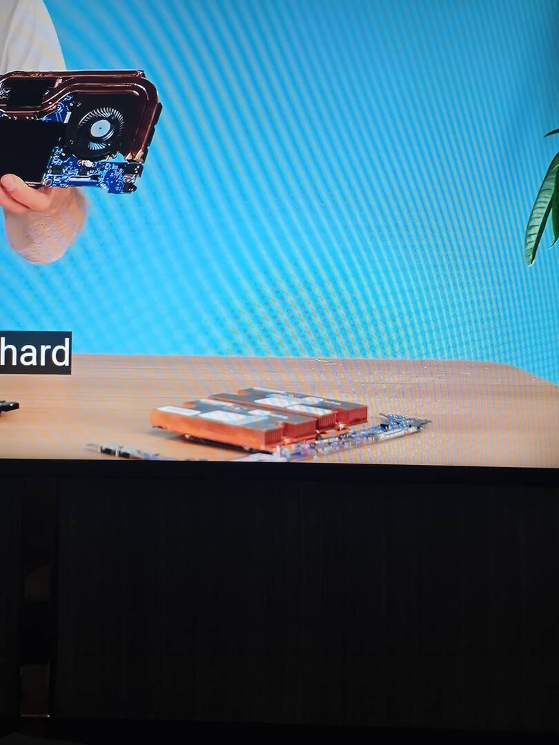
is that a custom heatsink?
Posted : 26/08/2026 10:06 am
After rewatching Matt's video, I realized he also used a type c to HDMI cable to boot into BIOS. Se we have found a solution! To get into BIOS without internal display.
Posted : 26/08/2026 10:08 am
I think I may have finally made some progress.
After consulting with Google's AI mode for more troubleshooting advice (as much as I try to avoid using AI, this did eventually get me to progress) I was able to confirm that the motherboard was successfully booting and going to BIOS. Caps lock/num lock on a USB keyboard was working, LED on a USB gaming mouse stayed steady and pressing [F10] then [enter] rebooted the board (saving and exiting BIOS).
I tried putting in a USB drive with a bootable version of Linux, which kicked on the GPU fan so it was running something. But the keyboard shortcuts, and commands that I used to try and blindly switch to an external screen weren't working. I also tried to modify the Linux startup files to disable the internal display but that seemed to kill the boot entirely.
I went back to the SSD with Windows on it and after futzing around with it for a bit I was able to undoubtedly confirm I was booting Windows by plugging in headphones and hearing the windows startup sound.
I tried blindly using keyboard shortcuts again but had no luck. But then I realized I could use the text to speech narration function of Windows to navigate where I was without a screen. Turns out I was stuck at a lock screen that needed an Internet connection to verify the PIN for the Microsoft account I used to set up the OS (MS forced me to tie it to an account).
Unfortunately, I didn't have the Wi-Fi card installed or an Ethernet cable were I was working on the board, and it was late so I tabled it. But hopefully once I get past the lock screen I should be able to navigate to the windows project function and push a video signal to an external screen.
Thanks everyone for the help! I'll update once I've hopefully gotten output on the external monitor.
I'm afraid that this still would mean that I don't have access to BIOS but at least it'll be an actually usable PC.
This post was modified 1 month ago by HiddenVector
Posted : 26/08/2026 11:23 am
Muzammil17 reacted

Hello @diy_perks! i really appreciate you shooting these videos.. I literally dont know how i would attempt projects like this without your two videos on this... I would really like to see the heatsink video as well, because the motherboards that i see often dont have the heatsink or coolers,
My laptop screen broke not too long after you put out this video, and i figured this is the perfect time for me to turn it into something with a nicer screen!
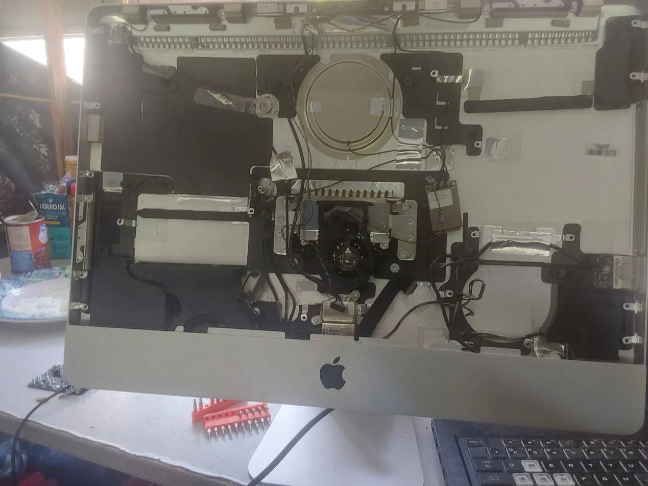
I'm gutting a 2011 21.5 inch IMac and placing my laptop (Asus TUF Gaming A17) mohterboard inside of it along with the parts required to turn it into an All In One PC... i found a really nice HP P244 23.4 inch monitor in a dumpster and i would LOVE to use it over the IMac in many ways (Its display takes 11 Watts of power, weighs 6 pounds, while the 2011 IMac display takes 44W of power and weights 20 pounds).. but that monitor would become advanced really quickly because the way the power supply and display boards are placed directly in the center of the display.. that would mean i would have to 3d print a case or fabricate some aluminum bracket and im not familiar with that stuff.. and it would also be really bulky...
I generally am a DIY person, but in the past, me underestimating the complexity of these things really came with many moments of failures or setbacks i couldnt account for... but this time, now with your video, and my new approach, i think this can be really fun!.
using a 2011 IMac is the sweet spot because:
1. the Glass that sits on top of the LCd display with magnets.. so no glue, noscraping or super sensitive issues
2. these IMacs have more space in the case that the more recent versions... the case depth is entirely around 32mm, and i get roughly around 26-30mm of height inside the casing depending on whether im at the center or side of the inside of it
3. USB ports are already cut out
The real hurdles are
1. finding a good place to place the sub plate without drilling any holes that ruins the aesthetic
2. getting the wifi and bluetooth radio frequencies to work in a completely aluminum chassi without drilling in antennas
3. finding speakers that dont suck and trying to face them forward
4. Ensuring that any other PCB board/ device i place inside this fits the height requirements to stay solid
5. trying to account for heat and create some airflow so i can still game on this thing
6. bridging all power together (trying to make sure that i can turn on all three elements with one push of a button. im taling the LDC display board, the amplifier board and my motherboard)
I'm going to try to use the screws that hold up the stand as the fastening point for the sub plate... that should be strructural with no issues.. and im also going to try to use the antennas on Apples' wifi card so i dont have to drill any holes......
but i really want to here what y'all think about this.. has anyone on here done something like this with an IMac? because i cant find anyone who has.... am i missing something in my build?.. im no pro on any of this and i just found this forum..
Posted : 26/08/2026 7:00 pm
@imp-inventor lol i know you weren't talking to me but im going to do exactly what you said you wouldn't do!. ill be sure to update y'all on the process... you make it sound easy to build cases for these.. do you have a 3d printer laying around or something? i wonder.....are you more familiar with working with metal than i am?
Posted : 26/08/2026 8:34 pm
Success!!
Once I hooked up the ethernet cable and set up the new PIN, it immediately displayed on the external screen. No more blind navigation necessary!
I do think I'm locked out of BIOS still but at least I have a working HTPC now.
Posted : 27/08/2026 2:53 am
@hiddenvector congrats!, have you tried the thunderbolt port, and a type c to HDMI cable, you should get the monitor to display BIOS.
Posted : 27/08/2026 6:19 am
@muzammil17 I did try the thunderbolt port with a type-c to HDMI cable but wasn't able to get to BIOS on the external. I'll try again later today now that the PC is functional.
Posted : 27/08/2026 12:37 pm