
Notifications
Clear all
Microphones & Mic Preamps
1,336
Posts
198
Users
335
Reactions
347.3 K
Views
I have a few questions, what power rating should the resistors have? It's not that relevant right?
I suppose the tolerance should be as small as possible preferably 1%.
I can also buy resistors specifically for audio, they all have 1W power rating and 1% tolerance.
It says that these ones have low inductance and low noise, they're roughly 1EUR piece.
Would these make a noticeable difference in our case or not?
They are H4P2K2FCA, H4P100RFZA.
I also found capacitors specifically build for audio like the UES1H220MPM and UKW1C222MHD.
Do they justify the higher costs or it's nothing noticeable?
Could we use a J304 instead of 2N4416 Transistor????
It seems that they have very similar specs but different body and much cheaper.
And for the sound board, would any do? Even the really cheap chinese one?
Or we need something better like BEHRINGER Guitar 2 USB?
Posted : 16/01/2023 7:33 pm
Hello guys. Have been trying to find an answer to the question that multiple people have asked, didn't find it here, but did find it in the discord server, so shoutout to the electricians over there who explains everything in detail.
FOR THE PEOPLE WHO ARE HAVING ISSUES FIGURING OUT WHAT TO DO WITH THE AUDIO INTERFACE 3 WIRES (Red, White and Black)

You basically combine the 2 signal wires together (red and white) as microphone inputs are mono and require 1 line, we combine them together and connect them into the OUT port on the makeshift PCB, and the Balck Wire e,g, GND goes into the respective GND port on the PCB.
Hope that helps any people trying to repeat this project as the video was extremely unclear on this, and Matt responded on the first page here on the forum to this question stating "this is common sense" maybe for electrical engineers yes, but not everyone here is an Electrical engineer and needs a little more explanation in order to try this project themselves.

Topic starter
The Behringer is my go-to at the moment as it *is* good, whearas my ultimate conclusion is that the Chinese ones are hit-and-miss unlike what I said in the video.
Resistors shouldn't matter too much for this application. 1/4w ones will be fine! 🙂 I also don't think you'll notice any special caps either.
The J304 transistor will work for sure, but it may have slightly more noise. I'm not sure if this will be noticeable over the noise introduced by the voltage isolator however. The J201 / J202 might be a better choice.
If you want the *best* noise performance a LSK189 is perfect, but you will only notice the difference if you operate the circuit from a set of batteries or have an EXTREMELY good power filter circuit (I'm still working on the latter for version 2).
Thanks for adding that here!
Posted : 17/01/2023 11:07 am

Hi Matt,
I had a brief look at your circuit when you first posted this and I noted at the time you're using the *worst* possible component right in your signal path.
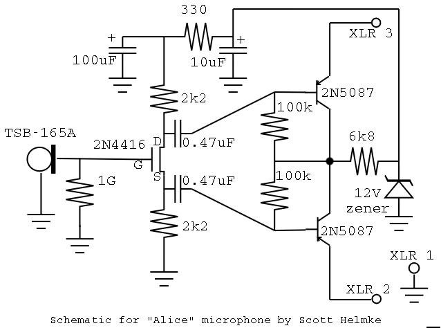
Since I've tracked down the original circuit now (there are many copies on the Internet) which is by Scott Helmke for his Alice microphone. Seems a lot of people don't know "what" an Alice mic is, but it looks like Scott names his microphone designs.
Yeah, I know that doesn't look like the one you have with the 15v monolithic voltage convertor and the rather dishy instrumentation amp, but the front end is still the same thing.
The first thing to note is that the 2N4416 can be replaced with a 2N3819 in most applications (perhaps here too) and that might be easier or cheaper as they used to be a jellybean JFET. They lack the screened can, but as you've cut and disposed of that connection there's no benefit to that. It's also really only useful for VHF applications so a plastic T092 package should be fine.
It's interesting to note that Scott uses a 1GR (one gigaohm) resistor in the gate path. I haven't tried this but I can see the point of adding that for bias. Most circuits leave it out.
Further down the signal path, Scott has second-guessed himself and has written that the 2K2 resistors might be a little small. He suggests 5K6 but in either case, you need the absolute BEST resistors you can get as any noise here will appear at the output.
But what's this horrible component of which I speak?
Electrolytics. (Shudder).
These things are just horrible. You can get HiFi electrolytics but they are expensive and I question if they are that much better. Further still, they are prone to breaking down with age (10+ years) and that will create odd issues over time.
Your version creates a high-pass filter formed from a 22uF N/P electrolytic with the 3K9 input to the THAT1512 instrumentation/hifi Op Amp. Excellent choice by the way.
But here's the thing: 22uF with 3K9 has a 3dB roll-off at 1.8 hertz which is well into the subsonic and I expect far below what such a capsule could capture. Scott's here If I read his design correctly, rolls off around 3Hz because of the larger resistors (that's a very back of a napkin figure though).
A 3dB point of 18Hz (which is still below human hearing) can be achieved by swapping the two input capacitors for something more "audiophile" such as a 2u2 polystyrene film (cheap, easy to find) or even Teflon if you're into throwing money at this stuff.
https://www.soundtronics.co.uk/2u2-50vdc-10-polyester-film-capacitor.html
The 22uF at the output doesn't need to be NP either. You could substitute that will something else with the +ve side connected to the OUTPUT of the Op Amp. If there's a DC bias hitting the other side of this capacitor, there's something wrong further down the line...
I didn't check the input impedance of the DAC for the USB C side of things, but if it's more than 100k, which is similarly likely, you can replace that with a 2u2 poly film too. Someone else better than I am who has these to hand might be able to check my working.
I think these errors crept in when someone misread the diagram (a bit like Chinese whispers/Telephone) because a designer wrote 2.2uF rather than the accepted method 2u2 - decimal points are often lost like this with precisely this effect and we have 22uF which is only available in electrolytics.
Finally, you really should have an RF snubber in there. Doesn't need to be anything amazing, but it's there to kill any HF on the power rails that can fold back on the audio - or when there's a taxi coming past.
The large caps should (ideally) be LOW ESR. This is important to kill any noise on the supply lines. They don't need to be audiophile-grade but one tends to go with the other.
What I'm getting at here is there's no point in putting in a LSK189 as a front-end to a THAT1512 and then hobbling everything with electrolytic capacitors - even if they are "audio grade" because polystyrene or similar will invariably give measurable improvements at lower cost.
Stripboard isn't great either - it's easy though. Something like this really should have a ground plane but that's not practical unless we produce a PCB.
Finally, and this is crucial everyone, get a proper capsule! Like Matt, I've tried the cheap ones and they are cheap for a reason. We're only spoiling the ship for a happeth o' tar as is.
Take everything I say with a pinch of salt, I might be wrong and it's a very *expensive* way to learn!
Posted : 23/01/2023 12:13 pm
DIY Perks reacted
I have a few questions, what power rating should the resistors have? It's not that relevant right?
I suppose the tolerance should be as small as possible preferably 1%.I can also buy resistors specifically for audio, they all have 1W power rating and 1% tolerance.
It says that these ones have low inductance and low noise, they're roughly 1EUR piece.
Would these make a noticeable difference in our case or not?
They are H4P2K2FCA, H4P100RFZA.
1% tolerance is nice, but quite common these days. Pretty much any "jellybean" metal film resistor should be good here and 1/8W is fine. Resistors will always generate noise but unless you have pretty high-spec audio analysers you won't be able to tell. In days of yore (and this will make your eyes pop) albums such as Dark Side of the Moon, Sergeant Peppers etc. used mixing desks brimming with carbon film resistors and 741 op-amps. We've moved to NE5523 now for the most part unless you want super-duper-high-end.
There's nothing here that requires better than 1% as the differential signal does most of the work and that's decoded by the THAT1541 into a simple (unbalanced) line.
I've built a number of mics to deliver signals to balanced line inputs and (listen for the screams of tortured audio engineers) you can often get away without it!
Why?
Well to understand this you need to understand why balanced lines are used. Matt's design creates a balanced signal right at the head end (which is where it should be). I believe you can get capsules with FETs built in that also offer a balanced output and IIRC, the Panasonic WM61A can be modified to do the same. Primo probably do such a thing, but I've not looked.
But I digress.
The balanced signal is a genius way to eliminate noise on long runs of (even screened) cable by running the signal in two opposite phases (one down each of the white and red leads) with a common to the screen.
So our signal arrives at the (in this case) THAT1541 as -1 and a +1 which, if added together cancel each other out. In practice, there are always small, but usually insignificant differences but this design allows for that too!
Instrumentation amps are highly optimised versions of a differential amplifier circuit - you can build one with a jellybean op-amp like a 5532 and just four resistors. Figure 6 at this link:
https://www.arrow.com/en/research-and-events/articles/fundamentals-of-op-amp-circuits
And THIS is where you need those super-precise resistors because any "difference" error (common mode rejection error) will appear on the output. Devices like the THAT5141 do all that work - and it's going to save you a lot of headaches. I built these back in the days of Dolby Stereo to "decode" the surround sound channel which is encoded on the left/right signals in such a way that it should cancel out on the front sound-stage but can be amplified and fed to surround speakers.
In a balanced line like this one, one input remains in phase while the out-of-phase signal is inverted (back into phase) and the two are summed together. If you like the old "hot and cold", hot is IN phase whereas cold is 180 degrees out of phase. The cold gets turned into a hot signal and ... you end up with twice the signal.
Which sounds a bit pointless right?
Now consider this... any noise (passing taxis, badly earthed electrical equipment, etc.) but mostly mains hum from transformers gets on the hot and cold lines in equal amounts and in the SAME phase.
When you flip the phase of the "cold" signal, you also flip the phase of the noise riding on the cold signal. Add those two together and you get (drum roll) 2x your signal but any noise along for the ride gets cancelled out.
But that doesn't explain the poor-man's differential signal - in this case you put the audio down either hot OR cold of the XLR with a very similar result.
Sure, you don't get 2x audio since the unused wire is just "flapping in the breeze" but the noise signal still gets cancelled out by the differential input stage. Intuitively this seems ... wrong ... but it's a common practice I'm told.
Don't take my word for it though, try it for yourself!
Technically we don't even need the phase splitter at the head either for the same reason, but it does give that extra bite at the signal so the level is better (twice the signal, not twice as loud though).
So to answer your question (TL;DR) you don't need to break the bank on super-precision resistors for this build, if you want to improve things, look at my earlier answer re. those capacitors. This is where you could make significant (well, measurable) improvements to both noise and reliability. I expect Matt will make the relevant changes over time, this is his project and it's excellent as ever.
Take everything I say with a pinch of salt, I might be wrong and it's a very *expensive* way to learn!
Posted : 23/01/2023 12:55 pm
Topic starter
Thanks for the input! Very helpful (I’ve already read your comments twice there’s so much there).
To summarise (and please correct me if I’ve misunderstood anything):
Ensuring that the 2k2 resistors are metal film will improve noise performance, and a higher resistance should also be considered.
The 22uf electrolytic caps should be replaced with 2u2 (2.2uf) polystyrene caps for better longevity/performance, and a ceramic cap included between VE+ VE- near the opamp for RF suppression.
Low ESR caps for the power supply lines.
I’ve added these to my list of modifications for V2!
Talking of the original Alice design that the input stage is based on, I received an email earlier this month about my version of it after a viewer identified a problem and a potential solution, and I’ve been scratching my head over it ever since trying to wrap my brain around it and figure out why it hasn’t been brought up before.
Here’s what was written:
In the schematic, the source voltage is slightly negative because of the identical 2k2 resistors (the drain voltage is slightly positive by the same amount, it’s perfectly symmetric). At zero microphone output voltage, the nominal gate voltage is positive (0 Volts) compared to the source voltage, while normally the gate voltage of an n-channel JFET is made negative. This causes two problems: 1) the JFET may come in a non-linear regime, resulting in distortion, and 2) my 2N4416 allows 8 mA current at a zero gate-source voltage, while we can never have more than 30 V / 2 x 2.2 kOhm = 6.8 mA. So the gate voltage does not have any effect on the drain-source current at all, resulting in no output signal.
My solution is to increase the source voltage above the gate voltage by making the resistor between source and -15V larger. To maintain the balanced amplification of the THAT I left the circuit diagram intact, except I added a resistor between the source and the node where the source is connected in the current diagram (in the schematic, the resistor is in the horizontal line from source to circuit). I tried a few values, anything between 560 Ohms and 1k5 worked well, I settled for 1 kOhm. The circuit now works well on breadboard (in a metal biscuit can for shielding…)…
Do you have any thoughts on this? Asking as you seem to know a thing or two about circuit design!
The current phase splitter configuration looks ok to me, especially having had a look at this article: https://wiki.analog.com/university/courses/alm1k/alm-lab-phase-split
Posted : 23/01/2023 2:11 pm
@marcdraco this is an interesting experiment, so the caps are likely to make most difference in this case.
I already made an order for UES1H220MPM.
But I might just buy 2u2 polystyrene film caps just for the sake of testing, see if I head any difference.
Posted : 23/01/2023 2:22 pm
@axy_david Hi David. @diyperks Hi Matt,
I have what's widely considered to be the bible of foundation electronics - The Art of Electronics by Paul Horowitz and Winfield Hill. ( https://www.amazon.co.uk/Art-Electronics-Paul-Horowitz/dp/0521809266) and yes it's "HOW MUCH?!" but trust me on this, it's the only book you need if you want to work with electronics and understand what's going on.
It's now in its third edition and better than ever. Mine is the 2nd edition which I've thumbed until it's almost coming apart over nearly 30 years!
As I mentioned to Matt, the problem is likely that someone, somewhere dropped the decimal point because, at this sort of load impedance, you simply don't need a huge capacitor to keep your low end - you can see by the numbers, it was clearly intended to roll off at -3 dB for 18 Hz - just outside what we can hear but that missing point moved it to 1,8 Hz (I'll use a comma to keep it clear where the decimal point is).
Each stage (same in a filter) loads the previous stage by some amount: and when you're working with AC, you're into all manner of weirdness due to complex numbers (i.e. square root of -1).
As a guide (Horowitz/Hill) suggest the load impedance of the next stage should be 10x the output impedance of the previous one. This is what the JFET is doing to the capsule in fact - by presenting an almost infinite impedance to the very high impedance of the capsule and converting that down to an impedance suited for the next stage.
Electrolytics are not like ordinary capacitors which are two conductive plates with an insulator in the middle, they magnify the charge they can store using a special fluid called an electrolyte.
I actually did this myself (carelessly) about 40 years back (!) with what at the time was a VERY large electrolytic, 2,200 uF at 50v. I heard a hiss - couldn't work out what it was, turned around and saw my very expensive capacitor blowing a fountain of hot (and smelly) electrolyte all over my parent's front room carpet.
My folks weren't too happy about that I can tell you. That stuff is hell to get out of a nice twist wool carpet... (Oooops).
In fact, most times equipment fails, the fault can be traced to faulty electrolytics. I have a Denon amp here that conked one day. After some digging, it turned out that the SMT caps they used were "budget" ones and sure enough, one failed. ONE. And it killed the entire receiver. So I bodged a new one in and hey-presto, good as new. All for the sake of a 10p (or less) capacitor.
Big Clive (on YouTube) is an amazing repair guy who takes cheap stuff to bits and shows you how they work. Definitely a channel to check out. There are many others, but I find Clive doesn't talk down to us (or assume we know more than we do). He also does some hilariously crazy stuff.
But long story short, electrolytics are capacitors that use "tricks" to get the capacity and that means they are utterly useless when precision is called for. You CAN buy audio-grade capacitors for cases where you might need to DC block where the next stage has a low impedance (say 600R) but for most cases, they are a waste of time and money. It's this electrolyte that makes them polarised. Non-polar ones are just two polarised ones wired in series. The problem with that is it means there are two capacitors of twice the value marked on (capacitors in series are like resistors in parallel).
What makes this worse - and your mileage may vary - is the way we "lump" components.
When you pick up a capacitor, what you think of as a capacitor is actually a capacitor in series with a resistor (the ESR) and an inductor, bypassed by a really small capacitor formed by the leads. At audio frequencies, the inductive "load" and parasitic capacitance is immaterial for all but electrolytics. These little differences can distort the sound. Can you hear it? I'm old and have deafness appropriate to my age - so I'd say no. You CAN see the effect on a digital scope of course, particularly if it has real-time Fourier analysis.
So take a 22 uF non-polar cap. That's really two 44 uF capacitors wired in series. So whatever downside there is to an electrolytic (a lot) is doubled and there are three in the signal path.
This is where the "lumped" inductance and ESR come into play. ESR in particular.
You can think of a typical electrolytic as being an "ideal" capacitor of (insert value here) in with a series resistor and in the case of some electrolytics than can be in the order of several ohms. This affects the charge and discharge time of the capacitor to some degree but it also causes the internal heating (resistance converts electricity into heat) and that self-heats the device.
This is what causes (cough) cheap (capacitors) to age and fail prematurely. Sometimes with a nice "pop" but often all you see is a little bit of electrolyte swishing around your nice board or the little cross starting to bulge on the top (that's the pressure release to stop them exploding).
It also affects their performance in filters - bottom line, don't use them unless you have to.
Take everything I say with a pinch of salt, I might be wrong and it's a very *expensive* way to learn!
Posted : 23/01/2023 4:54 pm
Hi Matt,
Metal film resistors are rather good these days. "When I were a lad" (lol) we had carbon film which were great sources of noise, metal film while not noise free (an impossibility anyway) are pretty good. Noise increases with impedance so that's always a consideration.
The main source of "hiss" in these circuits tends to come from zener diodes where used. Zeners are very noisy devices so you really have to "short" them at high frequencies with something like a ceramic capacitor (cheap, easy, reliable) to ground all that nasty hiss.
Now this is where we get to that FET phase splitter question.
The example you've cited is a BJT and BJTs don't work like FETs hence the confusion. BJTs are current-controlled devices whereas FETS (JFET and MOSFET) are voltage - technically "field" controlled.
But get ready for this one... JFETs like the 2N319 or 2N4416 operate in what's called "depletion" mode.
You bias a BJT into action by raising its base to around 0.6-0.8V (silicon) at which point current begins to flow between base to emmiter AND collector and emitter. (Note that electrons flow from the emitter to the collector which makes sense until you see that they are drawn using conventional current flow...)
So far so good and note that the voltage requirement is small.
Now consider a JFET. Analogous to the collector-emitter we have a channel from the drain (=collector) to the source (=emitter) but that's where it ends.
The channel on a JFET is always open when the gate is at 0v with respect to the source terminal. With the gate grounded (or connected to source) you get a constant current source/sink and you can even get these pre-made (current regulator diodes) although they tend to be more expensive than ones made with a BJT. A small source resistor can be added to improve stability over a range of voltages.
https://www.mouser.co.uk/datasheet/2/268/SA5_47-1591983.pdf
To bias a JFET we should really drag the gate down a little to bring it into its linear operating region - which is what the email is referring to. The usual way to do this is to add a large value resistor (say 1M) between gate and ground and a smaller one (2-8K) between source and ground. The exact value depends on the voltage drop across the entire network.
As current flows through the drain-source channel (gate is at ground potential), there's a voltage drop across the source resistor. This means the voltage at the source is higher (typically several volts) than the voltage at the gate and the JFET enters its active region.
The way I think of it is that by "sucking" charge away from the gate by making it more negative than the source, we close the "channel". The more negative the gate gets with respect to the source, the less the JFET conducts.
And this is where that gets sticky because JFETs are awful when it comes to manufacturing spread. The pinch-off voltage may vary from -3 to -8 volts for devices of the same type and batch (my example is the 2n3819), and that is further determined by the drain-source voltage.
In the email the writer states his FET allows 8 mA to flow with the gate grounded. So some paper napkin figures: We've got a 30v supply total with a total (fixed) impedance of 4k4. The short circuit current for that is 6,8 mA. If we assume that the channel conducts like a short circuit, that means 6,8 mA through each 2k2 resistor for a voltage drop of 15v a piece. That means that the gate is biased at -15v. (The impedance [RDS] of a typical FET like this, gate = 0v, is about 150-300R. At -15v though, it's pinched right off which would explain why it's not working for some.
The phase splitting needs to be dead accurate (if this works, we would normally use 0.1% or better resistors) to ensure that the (pickup) noise component is eliminated by the high CMMR of the THAT1541. If it isn't there's no point having all that extra circuitry.
I haven't done enough work with this type of capsule to give you a definitive answer. I expect it works because the charge on the capacitor causes the gate-source voltage to change slightly, but I have to wonder if a better design would be to use a properly biased network to drive the FET.
I'll consult Horowitz & Hill and see if there are any reliable biasing schemes that don't mean sifting through a box of JFETs and testing them for performance.
An old mate of mine (Iain Sharpe) translated Paul Falstad's circuit simulator to Javascript. He has some examples of JFET use there too, although I can't help wondering if your (rather genius) DIY scheme for encasing everything in a brass Faraday cage eliminates the need for a balanced feed directly from the head end. It might be easier to construct just an impedance matching circuit and let the screening take care of the noise.
This is really a stream of conciousness, not hard science, so please do take it like that.
Being the cheap SOB that I am (cough, cough) I'd probably use a 2n3819 for the impedance matching and "amplify" the resulting signal using a NE5532 configured as a follower. Even that might be more that we need - it's a matter for experiment. The NE5532 is a stereo op amp for audio use but there are others like the (cheap) TL072 which have JFET front ends and are fairly low noise. Improved versions of these are available from Burr-Brown but be prepared to crack nuts betwixt thine cheeks when you see the price! 🙂
Oh, I just looked at Scott's design - the total voltage is 12v across the drain-source which puts the gate at (roughly) -6v which is probably why that works. I'm guessing - I'll nip and see of these other ideas work and get back to you.
Take everything I say with a pinch of salt, I might be wrong and it's a very *expensive* way to learn!
Posted : 23/01/2023 6:46 pm
"Hang on a minute, I have an idea!"
Every time my (design) partner heard me say that sort of thing he would cry softly because it invariably meant, a whole new show.
FWIW, here's my thinking.
I've looked at the original Alice design and I'm honestly a little foxed as to why Scott used a JFET as a phase splitter. At 12V (rail-to-rail) that does seem to put the JFET into its linear region by byassing the gate to -6V, but that is likely hit and miss too.
Which got me thinking, why even bother?
WORT!?
Hang in there for a moment though and I'll run through my thinking - some of which I've confirmed by experimentation with some nasty FETless Chinese capsules. They're still electrets so don't need a biasing voltage (I have better one which requires about 48V to get it out of bed).
Differential lines (which are typically supplied over twisted pairs, although they don't have to be) are intended for situations where you have a low level signal that could be perverted with a lot of electrical noise. Be that radio or ****ing mains hum. But such cables might run for tens of metres. The cumulative impedance of that cable which can be in the high single digit ohms act like a huge radio aerial. Not good.
But your design only features a comparatively short and well-screened run, there's no need for a balanced line encoder nor decoder. If you don't have one, you don't need the other. I'll get back to that in a moment, so buckle up! 😉
The stronger the signal is (in effect, the lower its impedance), the less you need to worry about noise. Any noise is simply swamped by the signal from the mic.
The Faraday cage formed by the braid and all the brass, pretty much takes care of the screening problem (although you do have to watch out for ground loops).
So can you run the signal direct to an on-board amplifier?
Yes and no.
Electrets have an excellent response compared to moving coil mics (Sure SM58 for example) which you have to bellow into if you want them to work. That makes them great for rockstars but not so great for well-spoken Englishmen and other sources like an acoustic guitar. You won't usually see a dynamic (moving coil) mic used for quieter sources, and this is where condensers come into their own since the moving mass is simply a sheet of mylar covered in a charged layer of gold.
The problem is that impedance-matching because, since they have a very high impedance, most amplifiers will load them and there goes all that lovely advantage.
OK, so we need something with a high input impedance and a very low output impedance so we can interface it to anything (and not have to wiggle around with electrolytic capacitors).
I used a jellybean TL072 (dual, JFET) for my tests and it's "m'eh" in noise terms - certainly, it would bring tears to your eyes but the sort of tears you cry when you hit your thumb with a hammer.
Thankfully there are audio-grade, dual-rail (so compatible with your existing design) what caught my eye was the OPA165x series which are pretty much state of the art (when you also consider they're affordable at just a couple of quid per amp).
https://www.ti.com/lit/ds/symlink/opa1656.pdf
The gotcha for some is that they're SMT but that might well be to our advantage - no one said this had to be easy!
I know this means some extra work (sorry Matt, truly) and it may even push the entire mic into a Mk. 2 version but I fully expect it would be quite practical to fit an OPA165 with at most two SMT resistors in the existing space. You'd also need to put three bits of ECW up the desolder braid (I LOVE that idea) because we'd need four conductors:
+15v, -15v, signal out and ground (via the braid).
I suppose it needs saying that those power lines need to be properly decoupled as they are running right next to a signal path. This isn't unusal though - phantom power shares the signal with the power line. It can be done that way too if you're feeling schwifty, but I'm a hack and too lazy to do the calculations. Someone smarter than I am could - but normal phantom power (48 v) has a series resistor which limits the amount of current we can draw and op amps tend to want a fair bit.
I should stress I haven't tried this circuit as described but it's basic stuff and should form an excellent starting point.
About 10 years back, I tried this with NE5532s for a hand-held design (phantom powered with WM61A capsules) and it worked well, but the 5532 is bipolar and not sufficiently high input impedance to not load the capsule we're using.
So back to foundations all that's needed is the OPA1656 configured as a votage follower (short the inverting input to the output) and ground the non-inverting one. If you're feeling brave you can configure a simple x10 gain with a couple of high-value SMT resistors to make an inverting amplifier, it's unlikley that would be necessary however as electrets already pump out a healthy signal.
A second OPA1656 in the base (a NE5532 would suffice too) would be convenient to amplify the signal before passing it to the ADC.
I'm spitballing again (filthy habit, I know) but the OPA1656 could even be biased to run from a single 15v line although that does mean a couple of extra resistors.
I have to get back to my proper job soon but this has my juices flowing, so unless someone else gets chance to take a stab at this, I promise I'll put it on my list. The idea of putting a "masthead" amplifier in such a beautifully designed arrangement really appeals and with phantom power, it would be simpler still... and no mucking around with differential signals. (If you really must have a differential, SMT is the way to go using a dual audio op amp configured in inverting and non-inverting x1 configuration. I honestly don't see the need but YMMV.)
Remember that phantom power doesn't have to be 48 v. It's that by convention (as is the 68 k resistor) but nothing says it has to be that provided you keep it ring-fenced in your own design.
Take everything I say with a pinch of salt, I might be wrong and it's a very *expensive* way to learn!
Posted : 23/01/2023 9:46 pm
I managed to find the correct desoldering wire! You want NTE# SW01-5 No-Clean Wick Width: .075" (1.9mm) There is another number on it: MIL-F-14256 Here is a direct link:
https://www.amazon.com/NTE-Electronics-SW01-5-No-Clean-Green-075/dp/B0195UW5FI/ref=sr_1_2?crid=13ARLJSBJPNJD&keywords=NTE%23+SW01-5+No-Clean+Wick&qid=1674511917&sprefix=nte+sw01-5+no-clean+wick%2Caps%2C502&sr=8-2
Posted : 23/01/2023 10:20 pm
Beginners should note which way the copper tracers are running on the strip board! You need at least a 95mm x 64mm, NOT A 64mm x 95mm because the copper tracers run horizontally instead of vertically like they should.
Another thing I found extremely useful and nice for mounting were some cheap brass kitchen plate hangers 😉 Here is a link:
https://www.amazon.com/Hillman-122048-Plate-Hangers-Protectors/dp/B000FSS3A6/ref=sr_1_3?crid=34P2W7OOPI1KB&keywords=brass+plate+hangers&qid=1674517511&sprefix=brass+plate+hanger%2Caps%2C461&sr=8-3
Posted : 23/01/2023 11:45 pm
Topic starter
Interesting commentary again! Particularly your train of thought leading to the use of an OPA OPAMP.
There’s actually a similar design of this on YouTube:
During my experiments for V2 of the circuit I actually had a go at building one. While it sounds pretty decent, the noise floor was a lot higher than the original JFET phase splitter design. Thinking I must have done something wrong I ordered a premade PCB version but unfortunately it’s the same.
I’m really not sure why this is the case, as the noise figures on the OPA spec sheet appear pretty decent. 5.1nV/HZ on the OPA compared to 4nv/Hz on the 2N4416 isn’t much on paper, but I’m hearing FAR more noise than that would suggest (unless the noise is coming from elsewhere?).
That said, I’d much prefer an OPA based circuit for simplicity. I particularly like how compact it could be, so if you do some experiments with this I’m very much looking forward to hearing about your findings!
It’s also worth noting that the JFET version manifests the same amount of noise to my ears as an NT1-A modified to use the same electret capsule (DC capsule bias voltage bypassed), so it has a lot of potential as even getting close (let alone matching) that is quite remarkable.
Note that this with the original circuit, only running off batteries to eliminate power supply noise (which is significant and needs improving).
Ultimately my hope is to use a true condenser like the NT1-A does, as they appear to have a much hotter output so in theory it should be possible to match an unmodified NT1-A’s noise performance (fingers crossed!).
Posted : 24/01/2023 5:12 pm

Since the replacement 1512 IC is stuck on processing forever - despite being in stock and "next day" delivery being available - I decided to start the fun part. There's 1mm mesh over 3mm mesh with a heavier wire gauge. Everything is soldered together and has continuity. I think I'm just going to solder a ground wire to it and run that and the ground from the capsule into the body, rather than risk a mechanical conection. The body will be mahogany, so I'm gonna have to use adhesive shielding sheet anyways. The chunk of mahogany and the shielding are just leftovers from a guitar I'm making:

The top is figured poplar, but the bulk of the body is mahogany. The lacquer hasn't been levelled or buffed yet, but the finish looks pretty level for something straight out of a rattle can.
Quick question though. If there's a version 2.0 with a better noise floor, are you gonna try to make sure the board fits within the dimensions of the current one?
Also: Am I right in assuming that I can take the output from the board to the USB A/D converter and connect it to a powered speaker or my PC line-in to rule out the USB gizmo as the reason it's not working? Mine had phono inputs, rather than a 3.5mm stereo jack. I'm not super familiar with phono stuff. Bit before my time.
Posted : 25/01/2023 2:37 pm
marcdraco reacted
I have wanted to build this microphone since the video debut in 2021. I bought (almost) all of the components to make two of them, but it got set aside and forgotten about until this week when a student of mine asked me what I knew about microphones, and I slid my box of parts off the shelf, and fired up the diyperks youtube video. Now we are full speed ahead to make these, and I am amazed to see how much activity there is on this thread as of late.
@diyperks Hi Matt! First let me say thank you for creating this project and keeping it alive. I would LOVE to test out your new design, but for now I'll stick with what we have and get on with it.
I have some questions about the "old one": First, what brass mesh did you use, and where can I get some of it? I cannot for the life of me find decent brass mesh. I've ordered it three different times hoping to get the kind of stuff you used (IE formable, thick wires, tight weave) but each time I buy more of it, I keep getting stuff that is more like cloth. (very fine wires, widely spaced, loose like fabric)
Second, what did you use for an encoder? I feel like I saw that info somewhere, but can't find it now.

Progress!
Posted : 25/01/2023 10:36 pm
Midnight_Vanisher and marcdraco reacted
Topic starter
I think the brass mesh I used had 1mm spacing or something of that kind of size. I get most of the stuff for my projects from eBay or Amazon so searching for "Brass Mesh 1mm" should bring up some options.
The encoder I used was a simple rotary switch, rather than an encoder. It's not entirely necessary to use a rotary one (you could just use a three position switch for example), or a POT, but according to the THAT1512 datasheet they recommend a capacitor along with it if used for gain control (not sure why, but worth checking out).
@Ashleigh That guitar looks amazing! Also, yeah, you can feed it straight into a PC line in if you like. It's a straight analogue audio signal so you can do pretty much anything you want with it 🙂 the plan for V2 is to make it much smaller than the original so it should fit into any casing you make now, yeah.
Posted : 26/01/2023 10:06 am
Midnight_Vanisher reacted
@diyperks I'm in the middle of a big project right now Matt, but I took some cues from Doug Ford of Doug Ford Analog Design, a guy who used to design mics for Rode no less!
Wow - was that an education?
It's amazing the stuff we can learn these days, isn't it?
I've jury-rigged a single-ended version which performs surprisingly well. As I mentioned, we really only need differential cables where there's a lot of noise and the cables are long (i.e. many metres) but let's forget that for now, I'll make a proper version of that one for the "cheap seats" like me. 😉
Phantom-powered but less complex because there are fewer parts and it really only works as an impedance matcher. This won't require the instrumentation op-amp but it will need split rails so we can make a 48v version or a 15v version just by swapping a few resistors.
And then, using Doug's genius, I intend to design a phantom-powered version with an optional boost that should work over very long microphone cables (or short ones) so it can drop right into your existing design with the THAT1514.
In fact, that's the one thing you perhaps didn't consider. I know this beautiful design was intended as a desk mic, but put a larger box on it and you have one hell of a recording mic for nature, orchestral or even vocals. One that would drop into a standard 48v phantom-powered professional rig and (as you've noted) perform like some of the best mics you can get this side of tens of thousands. (They use tubes and transformers apparently!)
Doug also noted that in one design at least, Rode (under Doug's team) included a balanced T network - essentially a high-pass filter in a feedback loop to, get this, boost the high-end from about 6 KHz by around 4 dB!
Now you and I obviously want a beautiful, flat response right?
Turns out that musicians often prefer mics with a non-flat response curve because they are (to quote Doug) creative people who are making music. Who knew?
I'll keep you posted but anything I submit will be Free and Open Source.
EDIT: Here's the Rode Studio Condenser mic - powered by a VALVE. A modern one of course, hand selected and aged by Rode for top performance (from Doug's mouth to our ears). It uses a -180 volt rail to power the valve... Egads!
https://www.gak.co.uk/en/rode-nt-k/5736
Several of Doug's other designs use a combination of a JFET impedance stage plus a bipolar class AB power amp (biased by red LED no less) to deliver some real punch.
Personally (and this is just me) I'm a fan of keeping it simpler so a JFET op-amp seems to avoid all that fiddly circuit board design since it already has everything we need, even with this we could use a guard ring to improve noise rejection. It's just that op amps are a bit greedy in terms of standby current which means they can be difficult to power from a standard P48 design which allows (usually) only allows a small amount of current (about 5-6 mA) before the voltage drops too unsable levels, so it's now a hunt for suitable parts for that version!
Take everything I say with a pinch of salt, I might be wrong and it's a very *expensive* way to learn!
Posted : 26/01/2023 2:21 pm
@ashleigh That guitar is amazeballs.
My son-in-law is making a replica of Dr. Brian (Queen) May's Red Special. Not quite perfect (we've bought the little pearl things you mark out the fretboard with for example) but wow, what a project that is!
It's a bit much for my skill level with wood, the blockboard isn't too bad but the oak and saple are so hard it's like hacking through brick! Incredible stuff.
Take everything I say with a pinch of salt, I might be wrong and it's a very *expensive* way to learn!
Posted : 26/01/2023 2:25 pm
Actually...thinking about the design used in the video...Having the shielding that close to the capsule, might be a source of some noise. I think some stand-off would be better. Actually, not a SOURCE of noise, I just mean that the current induced in the shielding by the very fact of the shielding doing its job, is gonna give the shielding it's own EMF, however small.
But I dunno squat about electronics beyond huge valve amps from wayy before I was born, and that's a different animal. If you don't bolt a transformer down securely, it physically vibrates because of the interaction of its magnetic field with the chassis, even though it's totally enclosed. So I could be totally wrong in the case of a bit of EMF from a nearby computer monitor.
Posted : 27/01/2023 2:59 am
@marcdraco Thanks. If you don't have a router, get one. It's probably the single most important tool you can own if you're making a guitar. Just cutting the truss rod channel without one, turns a 5 minute job into hours of work. You can cut out a pickup cavity to a better standard in a few minutes than you could in half a day using chisels. The only downside is that if wood knows it's been cut with electric tools, it tells the tone gods to make the instrument sound bad
Posted : 27/01/2023 3:08 am
I was wondering if anyone knew if I could use this resistor? 2.2 kOhms ±1% 0.125W, 1/8W Chip Resistor 0805 (2012 Metric) Automotive AEC-Q200 Thick Film I found it on Digikey https://www.digikey.com/en/products/detail/yageo/AC0805FR-102K2L/14286388
I want to use this for its small size so that I can create my own circuit board, and still keep a small form factor. However I am not sure whether or not this will overheat and burnout. I would also like to know If there are any other problems that may be presented if I use resistors this small?
Posted : 31/01/2023 10:32 pm
Perhaps this will be of interest to someone. I have finished my microphone after a very long time. The biggest differences are:
- I made everything out of copper (easier to work with than brass); for the ring I used the smallest standard air conditioner pipes that are readily available,
- I did not dismantle the USB audio card, so the box has three connections: Audio output, power input and external resistor
- I minimised the PCB and used a logarithmic series of resistors covering the whole THAT1512 gain (-6dB to 60dB, open, 10k, 3.3k, 1.2k, 560, 270,120,56,27,12,5.6)
- instead of building the whole microphone stand myself, I bought a cheap one and connected the ring to it


See another post, https://forum.diyperks.com/postid/3174/, for other details.
Lovely design that @pygmalian - Matt is wonderful at creating stuff that looks like a work of art but is as functional as the best "off the peg" gear. I'm quite jealous.
I'm so slow getting back to you. Life getting in the way as ever.
OK, so what I've found now (partly by experimental design and partly by boning up on JFETs because I was a bit cloudy there too). There are several noise sources - the worst one by far is the 50Hz pickup from local mains. That's taken care of by Matt's excellent shielding design.
Where I've gone back to basics can save a fair bit as there's no actual need for a differential signal over such a short run. Balanced cables are shielded but are intended for multi-meter runs where there's a LOT of interference. Not the sort of thing you're going to meet at home.
So, I went back to absolute basics and used a 2n3819 jellybean (mainly used as an RF amp actually). JFETs are way quieter than bipolar resistors and even a "cheap" one is more than adequate for the sort of noise we're dealing with here when you allow for the digital stage which will add its own problems.
Just two resistors, a 2N3819 and a 9v battery - that's IT - I was able to make a mic head that needed little or no shielding, no balanced lines ... nada. And the noise? I couldn't hear anything until I pushed the gain on my C100 video camera up and then the internal amplifiers made so much noise that was unbearable.
The microphone "head" with the three components drops the multi-mega ohm impedance from the condenser to effectively less than 100 ohms. With that sort of current capacity, the actual signal from the capsule utterly swamps any other noise. It's simpler, far cheaper and just as effective. An NE5532 would be quite sufficient to kick the signal to a 1v line level if you needed that, but the drive is quite sufficient as it is to make my camera overdrive.
I'll post details as soon as I can extricate myself from my cat - it's his bedtime and he won't leave me alone.
Take everything I say with a pinch of salt, I might be wrong and it's a very *expensive* way to learn!
Posted : 04/02/2023 10:27 pm
I was wondering if anyone knew if I could use this resistor? 2.2 kOhms ±1% 0.125W, 1/8W Chip Resistor 0805 (2012 Metric) Automotive AEC-Q200 Thick Film I found it on Digikey https://www.digikey.com/en/products/detail/yageo/AC0805FR-102K2L/14286388
I want to use this for its small size so that I can create my own circuit board, and still keep a small form factor. However I am not sure whether or not this will overheat and burnout. I would also like to know If there are any other problems that may be presented if I use resistors this small?
Honestly, resistors are the least of your worries at the signal levels we're talking about. Most modern resistors are good quality (even the nasty SMT ones that are produced by the million). Resistor noise will be swamped by other noise sources - probably beyond even Matt's circuits because them you're at the mercy of the USB recording system.
A high value (2k2) at this sort of voltage isn't going to be carrying that much current. Ohm's law. It's about 7mA at 15v and the JFET is unlikely to be drawing any more than that. Unlike BJTs. you can't just push an unlimited amount of current through them because they just max out. You can connect the source to the gate and that gives you a very accurate current source (or sink) although you have to find the value by measurement due to manufacturing spread. The 2N3819 I was doodling with earlier drew 7.1 mA from a 9v source - and not a drop more. That makes them really "stiff" in that they will hold that value over a wide range of voltages.
You have to stick within the device's maximum voltages of course, but JFETs are pretty tough little blighters.
Take everything I say with a pinch of salt, I might be wrong and it's a very *expensive* way to learn!
Posted : 04/02/2023 10:35 pm
Topic starter
I'd be interested to see your circuit! If the project can be simplified to that level it would be a game changer, I think!
Here are two articles/circuit discussions I've found interesting that might be helpful for extra insight:
https://www.planetanalog.com/amplify-small-signals-in-low-noise-circuit-with-discrete-jfet/
http://blog.audioworkshop.org/simple-jfet-preamp/#.Y7yabijP1Pw
Both are unbalanced, and I agree that it's not necessary to have a balanced run over such a short length (especially if we can make a smaller circuit to sit behind the capsule).
Posted : 05/02/2023 11:28 am
@DIY Perks
Have you ever considered a design that uses the computer's audio card? So that you send the output of the amplifier directly to the microphone input and power is supplied via a USB cable? Is that even possible?
I tried that, but it seems that my audio card does not recognise external microphones...
Posted : 05/02/2023 4:08 pm
I'd be interested to see your circuit! If the project can be simplified to that level it would be a game changer, I think!
Here are two articles/circuit discussions I've found interesting that might be helpful for extra insight:
https://www.planetanalog.com/amplify-small-signals-in-low-noise-circuit-with-discrete-jfet/
http://blog.audioworkshop.org/simple-jfet-preamp/#.Y7yabijP1Pw
Both are unbalanced, and I agree that it's not necessary to have a balanced run over such a short length (especially if we can make a smaller circuit to sit behind the capsule).
Happily Matt, given the level of complexity, I've dropped you a PM. It's probably a bit much (around 3K words!) with some ideas and rationale for improving this. I think (*know*) what makes this thing is the absolute beauty of the finished design. It literally took my breath away and I wanted one as soon as I saw your video!
For the impatient ("you looking at me?") here's a cracking start using a special-purpose MOSFET (imagine, not a JEFT) that should produce enough drive for a computer sound-card "Mic" input as @pygmalion is after. The FET might be tricky to track down. I've ordered a few from China although it should be possible to do this with something like a 2N7000 although the quality won't be as good. I have a 50-odd left from a previous job so I'll see what sort of performance they have.

EDIT: Agh. I goofed. That's a JFET - the symbol is a JFET but it's listed under MOSFETs in some of the data sheet libraries. Smack me with a haddock and call me Shirley. I've only been doing this hobby for 50+ years, you'd think I knew the difference by now.
The circuit is a bootstrapped follower which increases the input impedance by quite a large margin, I don't have the figures in front of me, but it's likely in excess of 500 Meg Ohms (why they've used such a large resistance in the bootstrap isn't entirely clear as bootstrapping increases impedance anyway! JFETs are a bit weird so I'm doing some revision to see how this works. Input and stray capacitances come into effect at these impedances so special circuit design is in order - this likely isn't the sort of thing we can knock up on a piece of stripboard.
I'm also designing a front end to work on much lower voltages which is obviously possible since a typical capsule can run from 1.5 to 9v so there's no reason I can see why we can't do that. (Famous last words!)
Take everything I say with a pinch of salt, I might be wrong and it's a very *expensive* way to learn!
Posted : 07/02/2023 4:29 pm
@DIY Perks
Have you ever considered a design that uses the computer's audio card? So that you send the output of the amplifier directly to the microphone input and power is supplied via a USB cable? Is that even possible?
I tried that, but it seems that my audio card does not recognise external microphones...
I've sent Matt my design notes but it goes on and on and on...
Some ports appear configured to "drive" low-cost electrets directly. These are the ones that you get in a lucky bag from eBay and have their own internal FET which I expect is a MOSFET due to the lack of gate bias.
My KiCAD is on the other machine (not my daily driver) so I hope you'll trust this scrawl - this is the way I power my Primo and WM61a capsules from a P48 phantom but this works just as well with a low-voltage source. A lot depends on what sort of parts you have lying around. The capsule doesn't require a lot of current so you can run these things from a 1.5 AA for weeks or months (literally).
Let's assume you have a 5v USB supply (oodles of current, up to 500mA on a standard output), but we only need a couple of mA to get things moving.

Driving a capsule with an internal FET requires 1.5-9 volts usually (higher is better) which means even the circuit shown in Fig. 1 is overcomplicated! R1 and the three forward-biased diodes give around 1.8v to the capsule via the external "gain" resistor. If you're powering this from USB, you can do away with R1 and the diodes but either way you should have some sort of supply decoupling that I haven't shown here but you'll find on Matt's drawings. The USB supply can be notoriously noisy.
R1 is chosen to give about 1-2mA of current through the diodes using ohm's law (for a P48 there's already a 6K8 in series with the supply so you add that in first) which leaves us something like 27 to 33K to allow a small drop across the 2k2 resistor. A 5V supply, as stated, only needs a load resistor of 2k2 to 3k3, larger values give a larger output swing.
There are some instructions here on how to wire a "stereo" jack to a mono mic using a typical sound-card wiring system although I would question their figures for input impedance. A low input impedance needs a large capacitor to allow for the voltage divider (high-pass filter) formed between the bias-blocking capacitor and the input impedance, so getting their suggested 22 uF electrolytic inside a 3,5 mm jack is likely going to require a file and a large mallet. Or maybe they got smaller while I've been out of the loop?
https://commsandsound.com/computer_microphone_faq
The passive filter calculator here is useful because it allows you to pop in your (expected) input impedance with a cut-off point - say 20Hz and it spits out the capacitor you need. 22uF is typical for a 600R professional setup.
http://www.learningaboutelectronics.com/Articles/High-pass-filter-calculator.php
10k input impedance which is more likely allows the use of the physically smaller capacitors you find in cheap tie microphones. The values I've used here roll off about 160Hz which is fine for something used for speech since our voices don't drop much below 200Hz and 3dB isn't a huge loss in real terms. The speech "frequencies" were defined years ago by the telecoms industry to be between 300 Hz and 3Khz (albeit for limited bandwidth devices). This is also why most computer microphones (except USB ones) sound dreadful with no bottom end to speak of.
Figure 2 is included for completeness since while it's widely used, isn't that well known in our part of the hobby. The two resistors *must* be closely matched (ideally 0.1% or better) for proper line isolation although 1% is sufficient for a lot of purposes. Their value is typically 50 to 600 ohms meaning the preceding DC bias-blocking capacitor has to be much larger.
How big? Think in terms of 160 uF for a 50-ohm load and since audio-quality capacitors of that size are going to run expensive they're the preserve of expensive gear. Particularly as tolerance of these things is a joke with 20%, either way, being typical. A 600-ohm load works out at the 22 uF capacitors in the existing design... yup, that's why they're that value - and have a predictive -3 dB point of around 12 Hz.
Take everything I say with a pinch of salt, I might be wrong and it's a very *expensive* way to learn!
Posted : 07/02/2023 5:52 pm
I've sent Matt my design notes but it goes on and on and on...
Some ports appear configured to "drive" low-cost electrets directly. These are the ones that you get in a lucky bag from eBay and have their own internal FET which I expect is a MOSFET due to the lack of gate bias.
Well, I do not have a problem with power. Matt's design also runs on USB power connected to both the disassembled audio card and the amplifier. In my case, I use two USB ports, one connected to the audio card and the other to the amplifier.
The problem is whether the output of the Matt amplifier is accepted by the audio card of the notebook, that is whether you can connect the output of the amplifier directly to the 3.5 mm headset socket. I can not check this because my notebook does not seem to support a headset microphone - it's probably something to do with the audio card's driver. If the notebook's audio card would accept the output of Matt's amplifier, you could just power the amplifier via the USB card and connect the output directly to the notebook's headset socket, and you would not have to buy a separate audio card. This is my idea.
Posted : 09/02/2023 11:48 am
Hi @pygmalion
I've adapted the following from Doug Ford's description of the Rode NT1000 microphone. The real thing will set you back nearly £300 so this is quite a decent solution (but keep reading to find an absolute stonker!)
You'll note there are some interesting bits here - particularly the class B power amplifier stage formed from the two transistors (NPN and PNP) which can be "small signal" transistors like a BC182 and BC212 for example. It's an interesting design with a bootstrap to keep the biasing in check and linearise the output. Something like this would easily drive a mic input even on a laptop. It's supposedly very good indeed and when I find some boards, I'm going to give it a try just for ****s and giggles. 🙂 🤣 🤣 🤣 🤣
I should repeat that while I've run this thing in a simulator, I haven't built it as yet.
The idea was to find something that works with simple supplies such as a 5V USB line without resorting to voltage converters and such which can add to the noise levels. It's highly likely this design will need a small capacitor across the NPN transistor in the power stage to compensate for the dominant pole which might cause it to oscillate. (According to Doug and he knows a LOT about this stuff). As shown this one rolls off at about 80Hz so it's not great for really deep vocals, etc although that does remove wind noise. It's a trade-off.

And without the "power" amplifier - this would still need something like an emitted follower to buffer the impedance down though. A simple emitter follower would do nicely but again... we're just adding more bits.

Ford used to use an SMD JFET originally produced for the CIA (true apparently) which came with a couple of diodes on its input acting as the 1G resistor. We can't get them any more so there's no point even attempting that. 1G through hole resistors are like hen's teeth and if you do find them, they're very, very expensive. The SMD parts are common and quite affordable though (about 30p a pop!) go figure!
Matt's design is overcomplicated (no criticism, just an observation) those parts are high-performance but dropping them onto stripboard makes the electronics gods cry.
TL;DR
By far the simplest method (particularly if you have the 15v rail splitter is to use an op-amp with a JFET front end. I've tried this with a jellybean TL072 (that's a dual, it's available as the TL071 as a single) both in 8-pin DIL packages - the basic circuit (sans the DC blocking capacitor and power rails) looks like this:

EDIT: the 10uF capacitor is the mic capsule, I just forgot to remove the annotation.
That's literally IT! Stick a suitable electrolytic on the end and you can plug that right into your mic input. I've used this very circuit to feed my Canon C100 cinema camera's mic input and even my little desk mixer so if it will drive that... If that doesn't drive your laptop's mic input something is very, very wrong. You can test a circuit like this with a high-impedance headset (not earbuds though, they're about 32-something ohms). I find the old earpieces you get with crystal radio sets are invaluable in this regard. Although an oscilloscope is certainly better if you have one.
But I can confidently say this works even with a 1M resistor - but it HAS to be a JFET (BiFet) op am like an TL071, TL081, 411... there's a lot of them but none have the quality we're looking for --- at least those don't. They're good, but not good enough. Bipolar amps like the NE5532 (the one I favour for audio use) don't have anywhere near the necessary input impedance and load the capsule down far to much.
However, there is a solution:
I'm going to put a circuit board together with a far better quality Op Amp (the OPA1641) when I can source the right components without someone taking my eyes out and coming back for the sockets. These things will run you about £15-20 but I don't think it comes in a 8-pin DIL, rather it's SMD only as are many parts these days. SMD is cheaper to make and easier for robots to build with. There's little call for small chips like I grew up with. It's slightly trickier to solder so I'll allow for that in the design and spec up the largest SMD resistors and caps I can find so you can solder it with a normal 12-15W iron.
Like the TL072, the OPA1642 is a dual version and the second amp can be used to add a 10 - 100x gain, low impedance output without breaking a sweat. But check those distortion specs! OMG!
You *can* run these things off a single supply but that means adding extra biasing bits, and if you already have the split rail... (which you do).
But honestly, when you boil this "problem" down to the nitty-gritty nasty, you can see that a "simple" modern, high-performance JFET input Op Amp is a simple way. I've seen designs that even drive these little fellas of a P48 supply which only delivers about 15mA total! That particular design is meant for P48 and drives a differential cable but you (and I) don't need anything so "studio".
Ultimately, what we're looking to do is stick a VERY high impedance to very LOW impedance convertor - which is what a voltage follower does - at the capsule. (That's the job of the FET in Matt's adaptation of the Alice circuit).
In fact, that's the job of the FET in the designs I've shown above. What appears to be missing from the Alice (the one Matt uses) is the resistor which is required to bias the FET. You can see it's pretty large - I've used a 1M - 2.2M but a 1 GIGA ohm is preferred. JFETs can't operate without this so I'm flummoxed as to how the Alice works. Even Doug Ford (who is one of the godfathers of this area) raised the same point. The small JFETs (not MOS as I'd assumed) absolutely must have a path from gate to ground (this forms a reverse biased diode) or they don't operate. Ford's assumes that the internal PCB (on these tiny electrets) produces a very large - but not infinite - resistance between gate and ground for this reason.
The only reason that comes to mind why this isn't working with your laptop is you've left out the DC block at the end? If the sound card doesn't block DC that will swamp the amplifier and you won't get a thing out of it. Probably won't be that but it's worth a look. It depends which bits you've cut from the Alice design. I assume you stopped at the USB-C DAC.
Take everything I say with a pinch of salt, I might be wrong and it's a very *expensive* way to learn!
Posted : 09/02/2023 8:28 pm