@russinkaffe from my understanding the size of the gaps doesn’t matter much.
I am using copper fabric and it seems to be working well.
(to be fair my microphone is not picking up sound unless I am right against it)
@holy_mcmully did you find what you were looking for ? I am looking for the exact same thing .
So I traded the J111 for the other transistor the one that is recommended and now it is worse than before, i got the 2N4416A.
It picks up nothing, switched back to the J111 and it is working. So now I am confused about next steps.
I was better off continuing to make knives. Would love to get some help, but alas. I have to yell for it to pickup anything.
If you figure out something please let me know. I may end up checking back on this forum in the future but for now I think i am done trying to figure this out.
im looking for an xlr output instead of usb since I already have an audio interface with preamp if anyone has a diagram for that, thanks in advance !
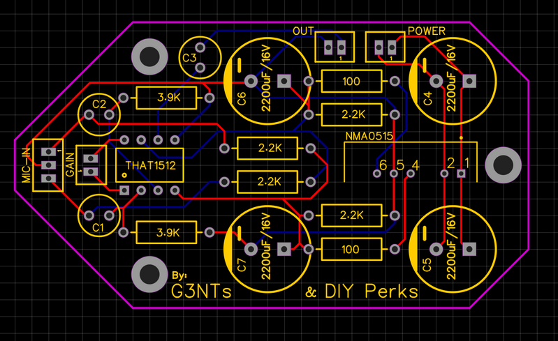
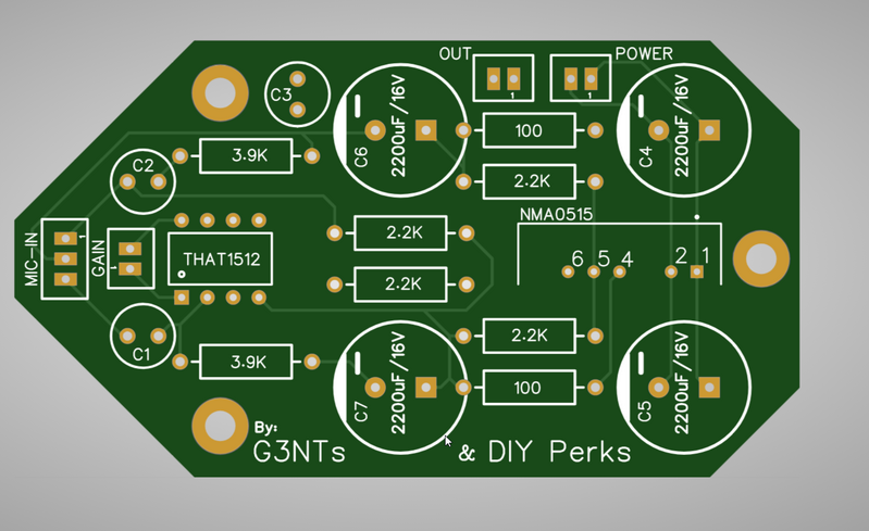
I am in no way an expert in making PCB's, but I made a PCB for the pre-amp. Files are on my google drive: https://drive.google.com/file/d/1-lWq-fnUQFZ48a6f5mhUU8FRPPyJGb5R/view?usp=sharing
enjoy
The design has not yet been tested, so proceed with caution!
Keep in mind the polarity of the capacitors. Make sure you follow the wire-diagram and not the stripboard template, as it seems people are getting issues due to (a printing mistake) the inverted polarity of two capacitors. ALSO ignore the polarity sign on the pcb design. Just follow the wire-diagram!
I am in no way an expert in making PCB's, but I made a PCB for the pre-amp. Files are on my google drive: https://drive.google.com/file/d/1-lWq-fnUQFZ48a6f5mhUU8FRPPyJGb5R/view?usp=sharing
enjoyThe design has not yet been tested, so proceed with caution!
Keep in mind the polarity of the capacitors. Make sure you follow the wire-diagram and not the stripboard template, as it seems people are getting issues due to (a printing mistake) the inverted polarity of two capacitors. ALSO ignore the polarity sign on the pcb design. Just follow the wire-diagram!
Your circuit traces are too thin, otherwise it seems fine at first glance. If your schematics are correct, at least it should somewhat work, but the signal quality you get might not be the best
Hi everyone,
I am quite new to electronics and i've tried my hand at the USB-c microphone, I followed the wiring diagram provided on the google drive but it didn't work. I then flipped the 2 polarised capacitors as it was mentioned previously in this forum and magic, it's working !
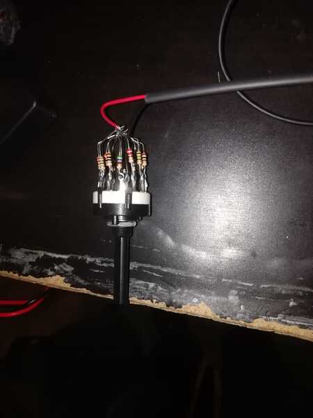
However, I have one last issue that I don't really know how to solve : changing the resistor's value with the rotary switch doesn't seem to do anything.
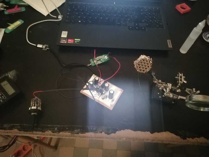
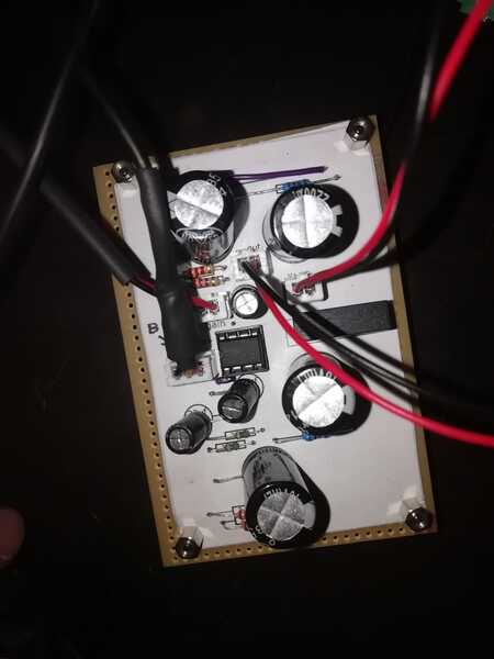
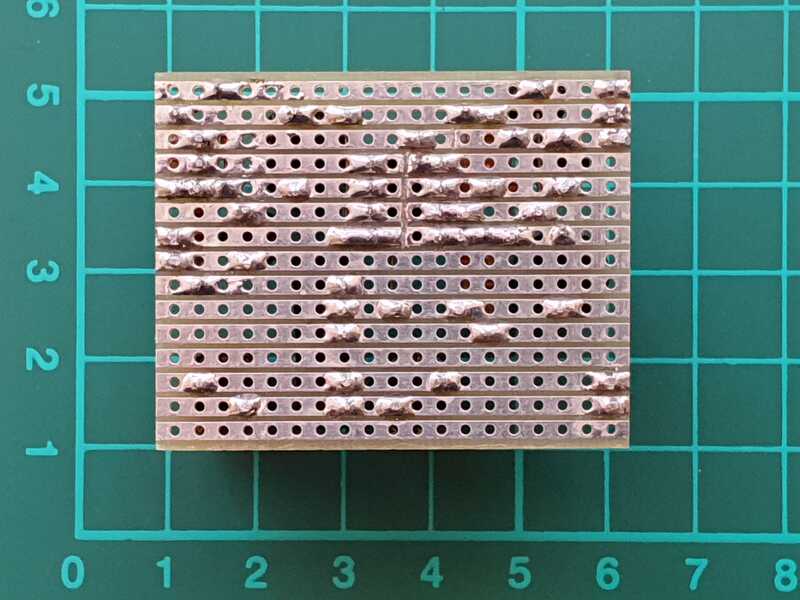
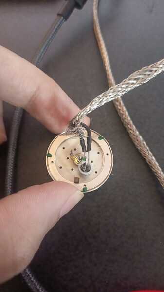
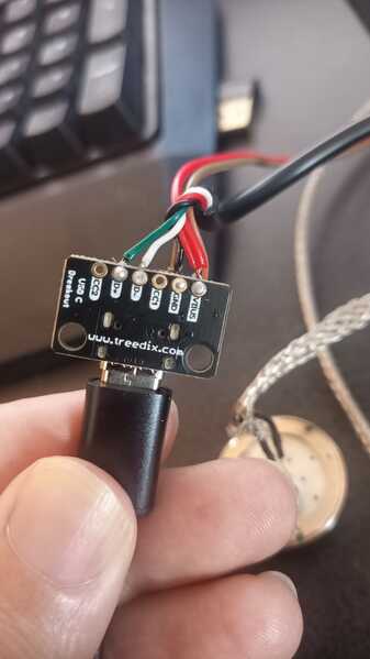
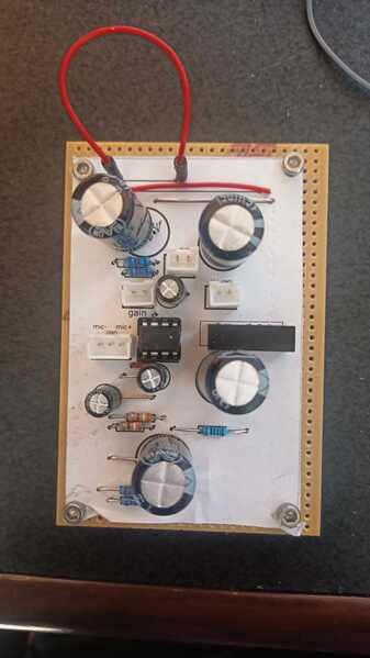
I've tried to match the resitor's value provided in the wiring diagram as closely as possible but there seems to be no difference in volume. I've attached audio samples at the quietest (560 ohm) and loudest (10ohm) volume as well as pictues of the system, if anyone had a similar problem I'd love to have feedback.
Thanks in advance.
@tom, I did check the required width for the amps going through the circuit. And based on that it should be fine. Can u elaborate why you expect them to be too thin? The THAT 1512 uses a max of 8mA. the JLI consumes 0.5mA. And I assume the rest of the components combined equal about the same combined. The 0.3mm thickness of the traces should support up to ~= 0.3A, With the design parameter of not heating the traces more than 10 degrees.
The only possible interference I might get from (thin) the trace width is:
- Ground bounce - The term used to describe the difference between an electronic device’s ground pin value and actual ground to which it is connected. This occurs due to conductor inductances between the device pin and the actual ground.
https://www.tempoautomation.com/blog/how-to-use-your-pcb-trace-width-to-improve-signal-integrity/
@someguy did u figure out which cables from the audio grabber need to go to the pcb? as there are 3 wires comming out, 2 wires going in?
@g3nts Hey, so I just finished this project, and I can confirm you want to marry the white and red wires into one signal wire, and then just connect the black to the ground. Works like a charm, and the microphone registers as a stereo microphone when connected to PC.
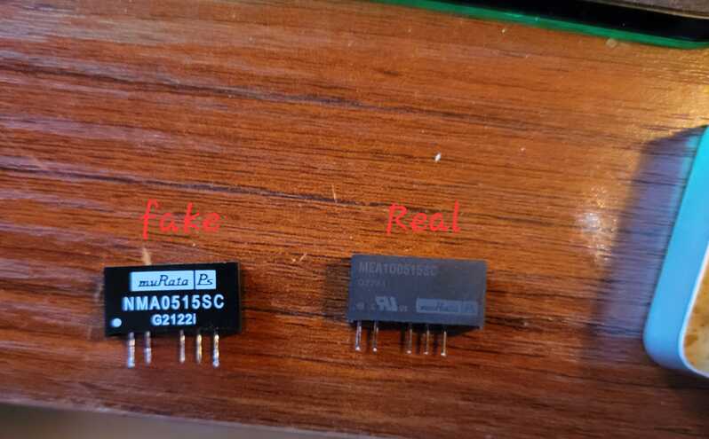
I did want to share a cautionary tale about ordering parts on e-bay. Make sure you get the real thing. I ordered the 5v-15v converter from e-bay, and turns out it was a fake. A fairly obvious fake after I found and ordered the part from Mouser. This sent me down a weeks long (really probably 4-5 hours then stopping in frustration and coming back with the multimeter) troubleshooting. I would see voltage coming out, then I wouldn't then I would again... Now with the real part in, the whole thing came to life. I know technically the part numbers are different on these in the image, but the printing should have given it away.
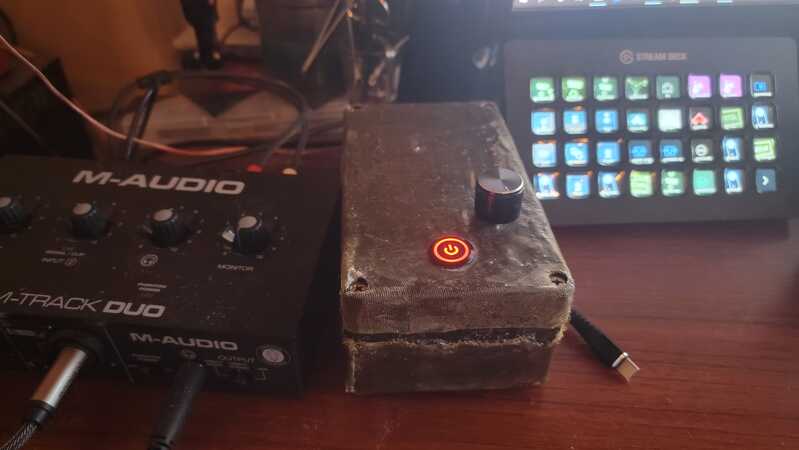
It sounds as good if not better than my Yeti Mic, and I am still sorting out the shielding/chassis grounding, so I think that sound will definitely improve. I also am working on plans to set up a vumeter on it just for aesthetics, since my box looks kind of like something from Fallout anyway, and could maybe pass as a geiger counter.
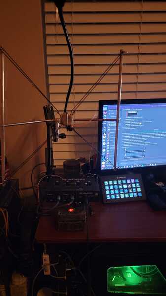
Anyway for the amp box, I just used a black project box from Amazon, then loosely molded some extra brass mesh around it, and used some translucent grey UV resin from my printer painted over it and sealed it with my curing lamp. I actually really like the wasteland look it gave it, and it made me not really want to sand and polish the microphone element, and just leave the excess solder on everywhere. This was my first time doing non-electrical soldering, making the frame and shock mount. I'll stick to soldering components thanks... 😀
Over all this really was a fun project and a lot of my gaming friends are jealous of how this looks and sounds. 10/10 probably will be helping some friends make these.
Maybe someone is interested in my experiences. I have done a few things differently.
- I ordered everything from AliExpress, including a cheap microphone for $2. Everything was fine except for the THAT1512 chip, which was a fake. I have already received a refund for that.
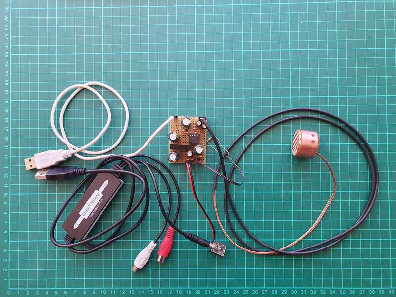
- I did not dismantle the audio capture card, but used the audio jack instead. This means I need an extra USB cable to power the unit.
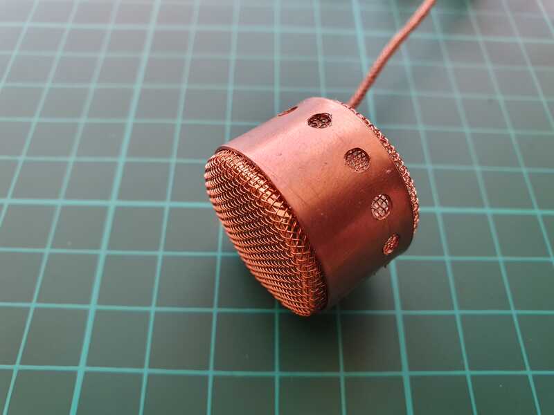
- I made the microphone housing out of copper, which is easier to work with and I always have at hand.
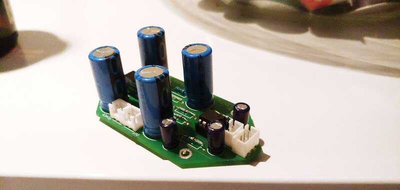
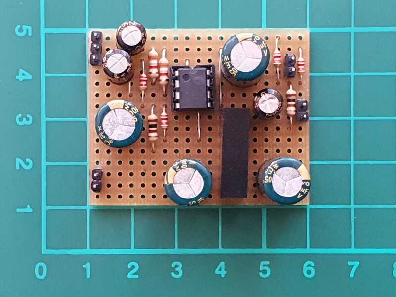
- I optimised the circuit board so that it is only 4 cm x 5 cm
The result:
- The sound recording is truly amazing - it even captures the sound of the lips opening. However, there is still some background noise; maybe I'll get rid of that when I build a box and put everything in a metal grid.
- I could not detect any axiality, the volume is the same regardless of direction. Maybe the problem is that the sound in the room is diffuse because of all the sound reflections, so axiality makes little sense.
See another post, https://forum.diyperks.com/postid/3338/, for other details.
@marpatdroid The one you wrote as fake is identical to the one I got off of mouser. That being said I'm getting zero signal from my board even though the NMA0515SC is putting out 15v no issues
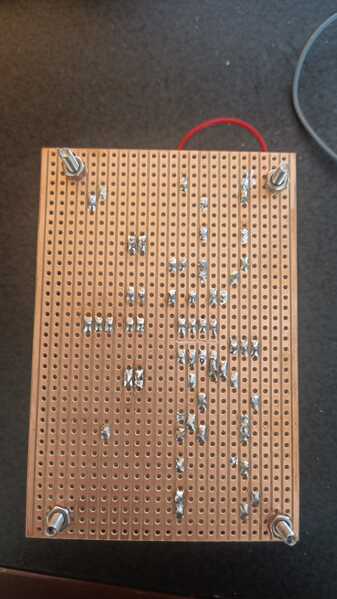
@diyperks I seem to not be getting any signal from my build, trouble shooting for about six hours and I don't see and issues with my circuitry. Wondering if I could pick your brain if you see anything wrong
. Needed to add, some spots in that picture it looks like there are shorts, checked already and nothing is shorting.
Ps, hey mods can you publish this please.
@hkh342 hmm maybe I just got a bum one then... My one labeled real is from mouser too... But I did notice the part number printed on it is slightly different.
Eitherway i now have a pile of in unused components because I didn't want to pay shipping for a bunch of small orders so I'm about to make a second one for a friend lol.
@hkh342 hey looking at your mic element, is your braid shielding soldered to the tab on the body of the capsule?
This could take a while to diagnose. Is there ANY sound from it at all? Even if you touch parts of it etc? One first thing you could try is get the highest value resistor you presently have access to (it should be 1Gohm really, but it's possible to test it with lower values) and link the microphone + connection to ground. This allows the FET to drain - mine worked without it but it's a start.
Looks great! Regarding directionality, make sure that the rear side of the capsule is fully exposed behind its mesh. If it's covered, it turns into an omni-directional microphone.
As for background noise, yours actually sounds pretty good! I'm presently designing an updated version which should allow for even lower noise. I've just made the order of some test parts - if anyone wants to help and experiment along with me the new JFET is one of these https://www.digikey.co.uk/en/products/detail/linear-integrated-systems-inc/LSK189-TO-92-3L-ROHS/14312168
I've since discovered that noise also occurs due to the voltage regulator/splitter, so I need to either work on better filtering for that or find another method entirely. I'm considering making the second circuit single-supply rail (rather than +/-15v) which should make it slightly cheaper to build and easier to source the parts.
Thank you for the reply.
Since my last post, I have realised that the noise also depends on the position of the microphone. If I hold the microphone very close to my mouth and of course reduce the gain, I have practically no noise.
600R & 10cm
50R & 40cm
So what is a typical distance from the microphone for this kind of use?
How did you test the directivity? In a room, especially a small one, there is a diffuse field, i.e. sound comes from all directions due to reflections. The back of the microphone is not covered. So it is either a diffuse field problem or the microphone capsule I used does not support directivity.
I am interested in further developments. But my main goal is to build a microphone that will allow me to measure motor rotations (by doing a Fourier transform of the sound). Other USB microphones have done really badly in this respect and maybe what I have created so far is already more than adequate. But I will not do any tests until I have built a microphone holder that will be attached to a camera tripod for simplicity, and a box for the electronics that I will design and 3D print.
Cheers!
I finally got everything together and hooked up correctly, however the voltage booster doesn't seem to be working properly. I get no sound and when I measure the voltage going into the component it reads 5v, however each of the other three pins also are giving 5v instead of +15v 0v -15v. Could this be a problem with my circuit or is it more likely to be a bad part? There are a couple spots that look like the copper strips are bridged but they are not. The 2-pin and 3-pin connectors are also upside down but I do have it wired up correctly. I'm somewhat new to hobby electronics so I am still learning, any insight would be appreciated!
Thanks for the help!
@diyperks So I've attempted to drain the FET, still getting nothing, went through and checked all of the connections again and it seems there arent any breaks. Do you know of a way to test to see if its the THAT? Also to answer your question, not getting any pickup whatsoever
@shankabee you sure there's no bridging between places there shouldn't be? If you find there isn't I'm guessing the 5 to 15v converter isn't functioning properly. Take a look at MARPATdroids post a few posts up
@diyperks Sorry, don't mean to be spamming you with replies. I've managed to get the mic to put out a signal after draining the FET, issue now is its only picking up very loud noises such as blowing into the capsule. Even with no resistor on the gain.
I got a replacement voltage booster and it is now working properly, however the output is so low you can't even hear it, but it is responding to my voice. I've tried just bridging the gain but it is still very quiet. I am not sure what the solution might be so I figured I'd ask! Thanks!
Greetings - I seem to be missing dimensions for your brasswork. Are they listed somewhere or do you have approx measurements for reference? Thanks!
@shankabee A higher resistance on the gain will actually produce more gain, so bridging will be minimum volume. What resistance are you using presently?
@sspargur It's probably best that you build it to the size of your circuit as it depends on the hight of the capacitors you've used etc.

