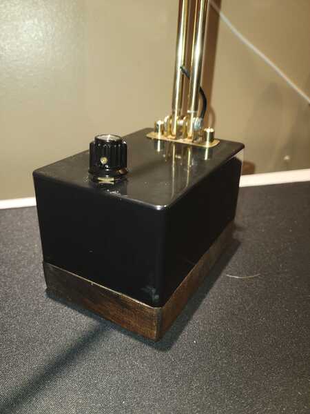
@diyperks Well I guess that would make sense then, I had assumed less resistance = more volume. The largest resistor I have access to currently is 3.9k ohm, which definitely boosted the volume noticeably but I'm going to have to order some larger ones, 1G ohm+. Assuming this fixes the sound level problem, is a rotary sound control still going to work or are the values too high for there to be a difference in volume? Also, when I have nothing plugged into the gain it can detect some noise, is this normal or is my circuit screwed up? Thanks again!
@shankabee A higher resistance on the gain will actually produce more gain, so bridging will be minimum volume. What resistance are you using presently?
@diyperks According to THAT manual, gain is 0.5+5000/Rg, so higher resistance produces less gain.
@diyperks used a bunch of higher resistors on the gain to no avail, still only picking up direct blows into the mic and tapping, also the THAT seems to be working only when placed into the socket reversed
@hkh342 That's not good... is the circle lined up on the side with the notch on its socket?
@diyperks what do you mean? Is the socket not bidirectional? I have the notch pointing to the right of the circuit and get nothing but backwards I get some signal just only loud pops
No, it's not - if you put it in the wrong way around you'll likely have killed it 🙁
@justalbin Hey, uh I haven’t started the build yet- waiting for all the parts, revising the video thoroughly, but I just wanted to ask you a question, as this seems quite difficult to get right, what type of potentiometer did you use as I know there are various types, if possible, could you please send a link, I live in the UK and yeah, thanks in advance igg
So, im almost done with the build, but two questions have come up:
First, with the audio interface:
When the audio interface was glued down, there were only a red, black and white wire left. (image below)
But only a red wire and a copper wire get plugged in:
So i guess one of them is GND and the other two make up the audio output. Which two of them need to be soldered together to make the audio output?
Second, the breakout board:
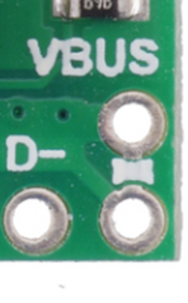
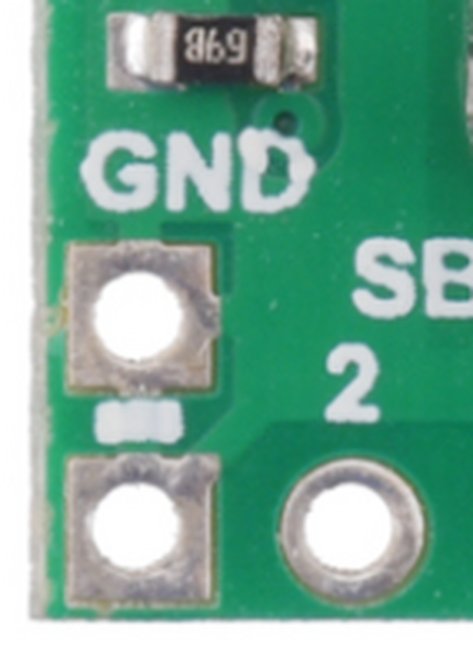
My breakout board only has one point each for VBUS and GND, while his has two for each, one for the USB cable and the other to supply power. Can I solder two GND wires to one GND point and two VBUS wires to one VBUS point?
Thanks in advance!
yes if u look at the PCB design online it should look like this so the 2 VBUS are connected to one another and the 2 GND are also connected to one another
https://www.pololu.com/product/2585 specs of the exact USB C breakout board he used
as u can see the circuit board is connected here: (VBUS and GND)
So if anyone here is only getting a little bit of sound when they tap the mic or yell into it or not at all, I have finally fixed the issue. Someone on here said something about the THAT1512 they bought being a fake. I bought mine from ebay and i finally bit the bullet and paid for the one off of Mouser ( https://www.mouser.ca/ProductDetail/THAT/1512P08-U?qs=9Udfh7QmL4sFBLonIQFgcw%3D%3D). Now I can hear my voice perfectly and the gain switch is working as well. Its only 10 dollars more than ebay and it should fix the problem.
I will check this out lol I bought my THAT 1512 for this guy (Link) on ebay and the sound is very low I have to crank up my volume to 100 but can still barely hear a whisper though I can still tell the mic is recording my words there is a lot of noise covering it up.
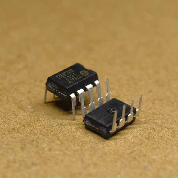
also, a note what do the numbers at the bottom of the chip mean? (pic below) I have 2 with identical prints. (I also presume its the batch number 3 of eBay sellers I saw were using this number 2137 4083)
@diyperks I accidentally broke both ground tabs off the body of the mic capsule that the braided cable gets soldered to. Is this a big problem and what can I do? I can order a new capsule but I live in Canada and it costs me 40 dollars.
@graydon-t Try and solder anywhere on the outer shell, or even strip some wire and stick it to the outer shell with tape to push it against the metal.
@diyperks I tried soldering to the shell but the solder wouldn't stick, I was worried that too much heat could damage the capsule. I'll definitely try using some wire, thanks for the advice!
I'm about to do a desktop test of mine. I don't know anything about electronics, so I've made a lot of assumptions. Are any (or all) of these assumptions incorrect?
1. If my capsule is in a larger grounded enclosure - ie: not wrapped in brass mesh like the one in the video - I'll need to run a separate ground from the body of the capsule to circuit ground for the mic to work at all. Edit. Ugh. I guess what those two great big tags sticking out the back are for. Nevermind. lol
2. if my USB converter dealie has stereo phono plugs as the audio intput, I need to connect both the ground sides to each other and both the signal sides, to get a mono signal. I know it sounds like a no-brainer. It does to me too. But it's the no-brainers that get you.
3. I can just short the leads that would go to the gain control, for testing or if I want to leave the control out entirely. Or should there be a resistor there?
Edit: Just saw a post about this. I stuck a 680r resistor in there for now. I may not bother with a rotary switch. Or I may use a 500r or 1k pot
4. I can just plug the audio converter directly into the computer and skip the breakout board for now, as long as I connect the VCC and ground from the circuit, to the USB plug VCC and ground
Also, are the signal wires from the mic - the ones labelled as mic+ and mic- interchangeable? I wouldn't think so, based on what little I know about transistors, but...ya know
Lastly, a question. Are the polarized caps shown on the drawing the wrong way round or not? Some people are saying they are, but surely everyone would be if they were. Or has the drawing been updated?
I think that's all
@graydon-t If you're stuck, maybe try soldering to the mesh on the front of the capsule. I think the body is aluminium, but the mesh seems to be stainless steel
Looks like your assumptions are more or less correct! You need a resistor for testing. I'd go with 100ohm otherwise it'll be quite quiet.
The mic wires aren't interchangeable as far as I know.
Just had a look and the 5v input caps are indeed in error on the schematic. I've corrected it and you can find the updated file on the project page.
@graydon-t If you're stuck, maybe try soldering to the mesh on the front of the capsule. I think the body is aluminium, but the mesh seems to be stainless steel
In theory that would work but there's a high chance you'd damage the membrane as it's so close to the mesh, sadly.
Looks like your assumptions are more or less correct! You need a resistor for testing. I'd go with 100ohm otherwise it'll be quite quiet.
Just had a look and the 5v input caps are indeed in error on the schematic. I've corrected it and you can find the updated file on the project page.
Ah, the schematic was incorrect, but not the layout drawing?
Hmmm. Not sure why mine isn't working then. I never even subbed any parts.The only difference is that my audio converter also had video inputs, which I don't see making any difference. I guess maybe I have the same fake IC problem. It's not the voltage booster dealie. At least I don't think so. I'm getting 15 - 0 - 15 at the output. I already checked for shorts and bad connections. Unless maybe at the transistor. I did that without flux, so the solder is a bit blobby. 🙂
I guess I can test the A/D converter with an MP3 player's headphone output, and make sure that works. And that just leaves the IC. I got it from a UK seller with 99.9% positive feedback over thousands of transactions, but most big EBAYers in the UK these days, seem to just be mass-importing all kinds of stuff from China, and working out of a storage locker on an industrial unit.
I guess I need to get a replacement just to troubleshoot. Unless...is there a way to check? Is there a measurement I could take with a multimeter that would be different with a bad IC? I assume not, cus it's an audio signal.
My computer recognises a "USB 2.0 microphone", but I think it's just detecting the A/D converter. When I run a mic test, it says it couldn't test because there's no mic plugged in. When I record in Audacity, I just get very faint noise. Even if I tap the capsule, nothing happens, so yeah. I think the amplifier IC might be the culprit.
Thoughts, anyone?
Also: Anyone got a list of op-amps than can be directly swapped? That 1512 is kinda hard to find
Ahhh! I think I see where I went wrong. The cap on the bottom of the layout drawing. mine is the wrong way around, cus it's not labelled, and I noticed that one side connects to the same strip as the pin labelled GND on the 3 pin socket, so I just put it in with the negative side connected to that strip, without thinking. The cap in the video is the other way around.
Edit. Nope. Still nothing. At one point I saw the VU meter on Audacity moving when I tapped the front of the capsule. On playback, it was just some scratching sounds.
The Datasheet for the THAT 1512 says a 10k resistor for 0db gain, but the max value I remember seeing on the rotary switch on the drawing was 560r
Nah. Tried with a bunch of values up to 1M. Nothing. I checked the transistor and no shorts. I guess it must be the Op-amp, so I'll have to try to find a substitute.
Meanwhile, to rule out the A/D converter, maybe I'll try running the audio out from the board straight to the line-in on my PC if I can find a spare 3.5mm jack plug
Yeah, it was the two voltage input caps on the strip board drawing (not the schematic) that help clean the power going into the voltage isolator.
Regarding gain again, you'll need to try 100ohm or lower. The higher the resistance, the lower the volume. Here's a good source of THAT chips: https://uk.farnell.com/that-corporation/that1512p08-u/ic-pre-amp-microphone-dip8/dp/1354162
Another thing you can try is adding your 1M resistor between the mic's output pin and GND for testing purposes. Technically it should be there, so that's the first thing to try.
@ashleigh I think that the IC chip is your issue, I put a link of for mousers website if your having trouble finding it. Before I got the new chip, I had tested everything, I even removed the brass mesh from the capsule. I was getting very low inputs, if I turned the gain all the way up in audacity I could kinda hear my voice. Also I ended up just soldering the desoldering wick to the brass mesh, as it was making good contact with the outside of the capsule.
@ashleigh I think that the IC chip is your issue, I put a link of for mousers website if your having trouble finding it. Before I got the new chip, I had tested everything, I even removed the brass mesh from the capsule. I was getting very low inputs, if I turned the gain all the way up in audacity I could kinda hear my voice. Also I ended up just soldering the desoldering wick to the brass mesh, as it was making good contact with the outside of the capsule.
I think I checked that link before. There's definitely a link to Mouser in this thread, but when I clicked it, the page was out of date. I'll just look via Google
Yeah, it was the two voltage input caps on the strip board drawing (not the schematic) that help clean the power going into the voltage isolator.
Regarding gain again, you'll need to try 100ohm or lower. The higher the resistance, the lower the volume. Here's a good source of THAT chips: https://uk.farnell.com/that-corporation/that1512p08-u/ic-pre-amp-microphone-dip8/dp/1354162
Another thing you can try is adding your 1M resistor between the mic's output pin and GND for testing purposes. Technically it should be there, so that's the first thing to try.
Ah, then I have them the right way around now.
I have a 100 ohm one in there at the moment. no joy.
The shipping and handling on that site is almost 3X the price of the chip. If I paid that, I'd have to kick my own butt on principle! I'll try Mouser, or I might try a substitute. From what I've read, that chip is overkill in terms of SNR for that capsule, so using a more available chip with a worse SNR is unlikely to even make an audible difference. I dunno how true that is. I guess I could get a substitute first, then, if the mic works but is noisy, I can try the 1512.
I'll pop a 1m resistor on the capsule anyways
Edit: Yeah, Mouser are pulling the same caper. Mouser UK want double the price of the IC. I dunno what they're paying for envelopes and stamps
.
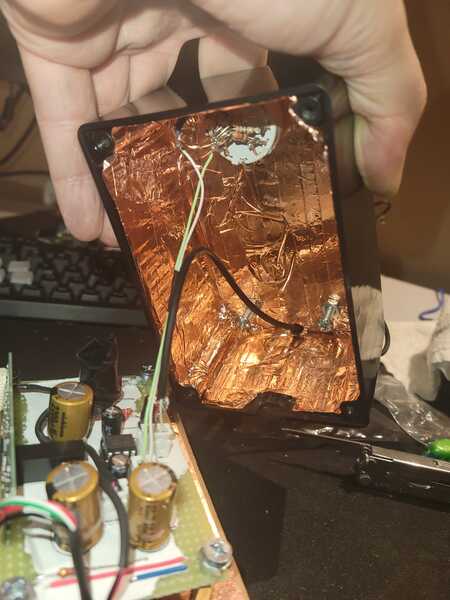
Well I thought I'd post my final results, I still need o-rings but that can wait. I have another mic capsule on the way so I'll probably wait till the 2.0 version to make another. I used copper emi shielding tape on the inside instead of the mesh
I finally got my setup working. I think the issue was the THAT component I purchased from ebay, I'm thinking it was fake. My solution after a lot of research was to purchase one of these: https://www.digikey.com/en/products/detail/texas-instruments/INA217AIP/486364 and that did the trick. I'm no expert on this so I don't know if this is a component that will damage the device down the line, however it works great for me with very little to no interference.
@diyperks thanks!, I just thought I'd ask, you've mentioned making a 2.0 version. Is that still in the works?
Yep! Should be out maybe in April.
@shankabee I think I got a fake IC, too. I just ordered the same part but from Mouser, but from everything I read, the INA217 is a direct replacement. Or rather the other way around, I guess. It boggles the mind to think that people would fake such a random obscure item

![20230112 185458[1] 20230112 185458[1]](https://forum.diyperks.com/wp-content/uploads/wpforo/attachments/285/thumbnail/337-202301121854581.jpg)
