
Notifications
Clear all

@ashleigh Yeah, whoops, I meant through-hole components. I'll look into trying that, then.
My worktable is a site of frequent detonations. Please knock so I don't start a Lithium fire when you startle me.
Posted : 29/06/2026 2:48 am

Songbird Michelle is considerably better than Matt's original.
You can't make it on stripboard because loads of the parts aren't available in through hole.
THT is going out which is an utter insult to people who are trying to learn as it creates a ridiculous barrier to entry. I already had a background (and I had a lot to learn) but there are numerous examples of what appear to be simple circuits that absolutely cannot be reproduced on strip.
The board itself could (in theory) be assembled at home but you need a hot air work station and a lot of patience.
I wouldn't and I designed the thing.
Take everything I say with a pinch of salt, I might be wrong and it's a very *expensive* way to learn!
Posted : 29/06/2026 5:56 am
@marcdraco Ahhhh...I'd better not try it, then. Thanks for the warning. In what ways is Michelle most significantly better than the original?
My worktable is a site of frequent detonations. Please knock so I don't start a Lithium fire when you startle me.
Posted : 29/06/2026 2:47 pm
marcdraco reacted
Mostly noise (S/N) which is definitively better, particularly at larger gains.
It's also USB-C (running at 12 MBPS) so everything is on the board. It doesn't have a monitor because I never added one (cost overruns and such).
And now my Apple Watch has conked. How am I going to tell the time now?
Take everything I say with a pinch of salt, I might be wrong and it's a very *expensive* way to learn!
Posted : 30/06/2026 10:12 am
@imp-inventor @wecan (I think that's the right handle, darn me and my blithering) hopefully should haves some field experience with it.
There's no such thing as noiseless in electronics (that would require physics to break and that's not on anyone's bingo card).
Michelle has a LOT of features that are available but simply aren't fully realised in this design (they're easy enough to add though).
The INA - (the thing that does what the THAT does) is similarly specced to the THAT1512.
There is space (and it's wired) for stereo but only one channel is available from the CMI108B. The I2S signals can be vampire tapped OR vectored off to another device (like a Pi Pico, STM32, ESP32 etc.)
The digitiser is capable of 192K which is twice the speed of the current offering (x 2 channels folks, I haven't forgotten how to count).
I guess the MAJOR change from Matt's (it's pretty much a ground up re-design) is the use of a very low drive voltage for the JFET. I could (conceivably) bump that back to 30v but that's even more cost.
Songbird uses a pair of chained LDOs (low-noise low-voltage regulators) to smooth out the USB voltage at the mic head until you'd be forgiven this was battery powered.
The original suffers not from poor design from on the board, but the utterly awful design of the USB power systems. These cables impress a LOT of noise on both rails and it's rich in harmonics - which makes it a nightmare to get rid of.
Take everything I say with a pinch of salt, I might be wrong and it's a very *expensive* way to learn!
Posted : 30/06/2026 10:26 am
Muzammil17 reacted

I was rewatching the instructional video on YouTube and forgot to solder the mic capsule ground to the copper insulation around the enamel coated wires. I've now done that. Do I also need to make sure I connect the copper insulation to the shield on my audio cable?
Posted : 13/07/2026 3:48 am
Not entirely sure what you mean by this.
Think of it this way. The mic has three connections in all, two carry the audio and the other is a "common" which is shared by both wires.
The third wire (the screen) connects to the brass ring/mesh at the head AND to the ground/0V connection at the board.
Take everything I say with a pinch of salt, I might be wrong and it's a very *expensive* way to learn!
Posted : 13/07/2026 5:09 am
Yes sorry, I wasn't very clear. Here's an image where I've circled the bit that I think I need to connect to the copper shield. My plan is to test at this point too before I go further. I want to temporarily put a TR plug on it to test I get a signal and the capsule works. I plan on plugging it into my focusrite amp (pic below). It has both line/instrument input and the option for 48v phantom power. Has anyone attempted something similar? I'm happy to go a different route if others have had success with simpler tests. It doesn't have to sound good, I just want to test I get a signal and can record my voice into my pc.
Thanks!
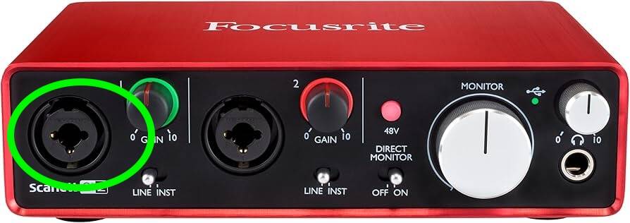
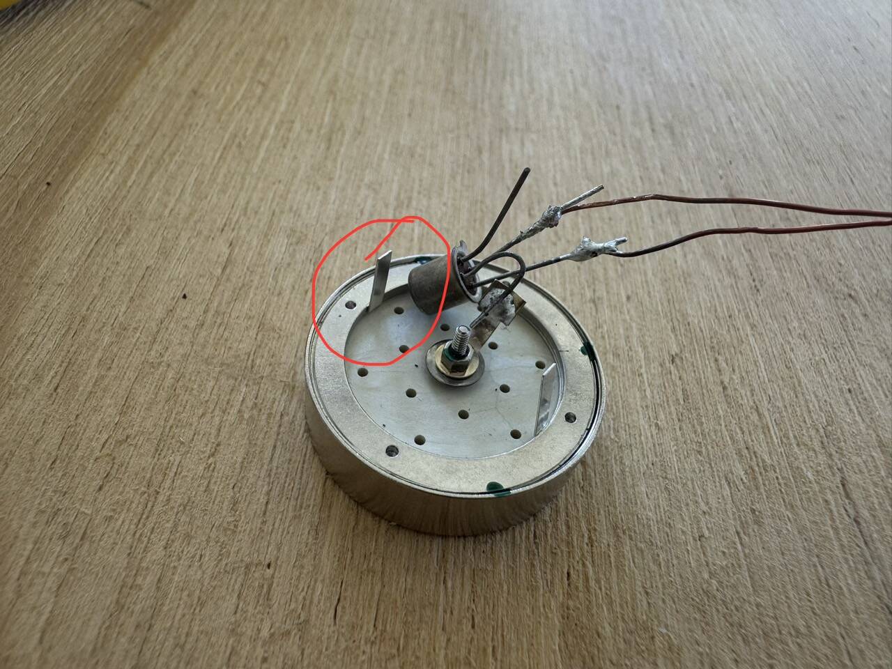
Posted : 13/07/2026 6:28 am
I did a PCB that soldered to the back of the capsule and converted it into a P48 compatible head but for most of us that's OTT.
What you have here though, that won't work (at best) and will blow your JFET (at worst).
If you just want something "Quick and Dirty" you'll need a small resistor (about 2,200 ohms or 2k2), a capacitor, 10 uF to 100 uF and a small battery clip. You'll need to put power into it you see; phantom is a bit of a queer animal and to use that we'd need to add a small regulator.
And then you're going to hit the OTHER problem with this capsule - it absolutely has to be screened. It simply won't work if you're anywhere near to an electrical supply because that thing would pick up Taylor Swift (if Travis didn't get there first, and even then I'm not sure)! 😉
Take everything I say with a pinch of salt, I might be wrong and it's a very *expensive* way to learn!
Posted : 13/07/2026 9:19 am
Songbird: Better Late Than ... 🤡
Seems I didn't post the files (months ago) so here's the current project, including all my rude remarks to myself because I forget stuff. The KiCAD schematics needs a bit of a clean and there are some oddments in there that I reall should have thrown away but it's hot. That's my excuse, excuse me while I down a few cold ones.
Design Philosophy
Michelle was conceived as a practical, high-performance microphone front end that could be professionally manufactured without requiring firmware development or specialist programming tools. Throughout the design, emphasis was placed on measured analogue performance, straightforward manufacture and long-term maintainability rather than implementing every possible feature.
Every significant design decision represents a balance between performance, complexity, availability and cost. Rather than pursuing the highest specification in every area, the objective was to produce a reliable, well-understood platform that performs consistently and leaves scope for future development.
Design Decisions
Four-Layer Construction
Michelle is implemented on a four-layer PCB using controlled-impedance routing where appropriate.
A six-layer stack-up would have offered additional routing freedom, improved power-plane partitioning and greater flexibility for future expansion. However, the additional manufacturing cost was difficult to justify for the intended audience.
The four-layer implementation provides an effective compromise between analogue performance, signal integrity and manufacturing cost while remaining suitable for small-volume production.
Analogue Front End
The analogue performance of Michelle is centred around the Texas Instruments INA849 instrumentation amplifier.
The INA849 was selected because it offers exceptionally low input-referred noise, excellent linearity and high common-mode rejection, making it well suited to low-level microphone signals. Although significantly more expensive than conventional audio operational amplifiers, its performance justified the additional cost for the primary signal path.
Rather than attempting to compensate for a noisier front end elsewhere in the signal chain, the design philosophy was to preserve signal quality from the point where the microphone produces only a few millivolts. Once noise has been introduced at this stage it cannot be removed later. For this reason the JFET operates in a modified Common Source mode vs. Matt's original.
For cost reasons, the default build populates a single INA849, providing a high-performance mono input suitable for the majority of voice recording applications. The PCB layout, however, retains provision for a second INA849, allowing a stereo variant to be constructed if required.
The analogue circuitry surrounding the INA849 was developed through practical measurement and refinement. In several areas, the final implementation differs from more conventional reference designs because testing demonstrated measurable improvements in overall signal-to-noise performance.
The limited supply voltage rails (+/- 5 Volt) restricted choice further, and left the THAT151x series out of the picture. Not that these are NOT drop in replacements as they follow a non-standard layout. Gain equations can be found in the datasheet but it's currently "fixed" at 100 R giving an overall gain of around 500 (54 dB). It's a slightly arbitrary value as I've found it's better to adjust the volume in the digital sections as an external resistor can pick up external interference.
USB Interface
The CM108B was selected as the USB interface for several practical reasons.
It is inexpensive, readily available and requires no firmware development, programming hardware or software toolchain. Once assembled, the board simply enumerates as a standard USB Audio Class device.
Although more capable microcontroller-based solutions exist, they inevitably increase both hardware and software complexity. Michelle was intentionally designed so that builders interested primarily in analogue electronics could assemble and use the board without first becoming embedded firmware developers.
The CM108B is also a mature device that is expected to remain available for the foreseeable future, reducing the likelihood of future redesigns caused by component obsolescence.
Clock Architecture
The PCM1809 ADC is capable of operating at significantly higher sample rates than are available in the default implementation.
In Michelle, however, the I²S clocks are generated by the CM108B. Consequently, the effective sample rate is determined by the USB interface rather than the converter itself.
For the intended applications of speech, streaming and general-purpose microphone recording this presents no practical disadvantage, whilst allowing the design to remain simple and robust.
Should a future revision require crystal-locked operation or higher sample rates, the modular architecture allows the digital interface to be replaced without redesigning the analogue circuitry.
Analogue Power Architecture
Although the CM108B provides internal regulated outputs, these are intentionally not used to power the analogue front end.
Instead, Michelle generates the microphone input bias using dedicated external low-noise regulators. A standalone 3.3 V LDO supplies a second 1.8 V regulator, producing a clean and stable bias voltage for the input JFET.
This approach deliberately separates the analogue input stage from the USB interface and its associated digital switching activity. Whilst it increases component count slightly, it significantly reduces the opportunity for USB-related noise to couple into the microphone signal path.
At the highest gain settings, a small amount of residual USB-related noise may still be measurable. Under normal operating conditions this remains well below the microphone signal and has no practical effect on recording quality.
Earlier prototypes investigated a fully differential input arrangement. Whilst this offered marginally improved common-mode rejection, practical testing demonstrated that the revised bias arrangement produced a better overall signal-to-noise ratio for the intended application. The final design therefore reflects measured performance rather than theoretical optimisation.
Analogue Supply Rails
The INA849 instrumentation amplifier is operated from dedicated bipolar analogue supply rails generated by the Texas Instruments LM27762.
Although Michelle is powered solely from the USB 5 V supply, the analogue front end was designed to avoid the compromises associated with single-supply operation or virtual-earth techniques. The LM27762 generates the positive and negative analogue supply rails required by the INA849, providing improved signal headroom and allowing the amplifier to operate around true ground.
These rails are used exclusively by the analogue amplification stages and remain isolated from the digital power domain wherever practical.
This arrangement complements the independent JFET bias network, which is generated separately using dedicated low-noise LDO regulators. The two systems perform different functions: the LDO chain establishes a clean, stable bias for the microphone input stage, whilst the LM27762 provides the bipolar operating supplies required by the instrumentation amplifier.
Separating these functions simplifies the analogue design and minimises the opportunity for digital switching noise from the USB interface to influence the microphone signal path.
Modularity
Michelle was intentionally partitioned into independent functional blocks comprising:
- Analogue microphone front end.
- PCM1809 analogue-to-digital converter.
- CM108B USB interface.
The interfaces between these sections remain accessible wherever practical.
The I²S bus is exposed through drilled test points designed to accept a modified 2.54 mm pitch header. By removing the associated link, the digital audio stream may be intercepted for development or experimental purposes.
The Master Clock is also available as a monitoring point. As this clock is generated by the CM108B, it is provided as a tap only and is not intended as an external clock input.
These facilities exist primarily to simplify development, measurement and experimentation. They are not intended as permanent expansion interfaces.
Future Development
The modular nature of the PCB makes it suitable as the basis for derivative projects.
Potential applications include:
- Stereo variants by populating the optional analogue channel.
- Alternative USB interfaces based on programmable microcontrollers.
- I²S-based audio processing platforms.
- Analogue-only microphone preamplifiers.
- Experimental digital audio interfaces.
These configurations fall outside the supported build but were considered during the original layout to ensure the PCB remained flexible without compromising the primary design.
Development Approach
Michelle was developed through practical measurement and iterative refinement rather than strict adherence to reference designs.
Where alternative implementations were investigated, the version adopted was selected on the basis of measured performance, manufacturability and overall usability rather than theoretical specifications alone.
The intention was not to produce the most complex microphone interface possible, but to produce one that performs reliably, is straightforward to manufacture professionally, and provides a solid platform for anyone wishing to understand, modify or extend the design.
The full KiCAD "dump" as a ZIP.
And the files you need to order.
Board "stackup" is JLC04161H7268 - 4 layer, impedance controlled. That's a no-cost extra but it's NOT an option. The USB needs an impedance control or it won't work with this design.
This post was modified 3 months ago by marcdraco
Take everything I say with a pinch of salt, I might be wrong and it's a very *expensive* way to learn!
Posted : 13/07/2026 11:11 am
Muzammil17 reacted
A Starting Point, Not the Destination
Michelle should not be viewed as the final word in microphone interface design. Instead, it is intended as a practical, well-engineered starting point for anyone wishing to explore high-quality analogue microphone electronics.
In many respects, Michelle is the spiritual successor to the original design, incorporating the experience gained during its development whilst taking a completely different technical approach. Although the architecture and component selection have changed substantially, the original objective remains the same: producing the cleanest practical microphone front end from readily available components.
Builders should not feel obliged to source expensive specialist capsules. Michelle was designed to perform exceptionally well with readily available electret microphone capsules, making the project accessible without compromising performance.
Although JLI do not currently manufacture a cardioid electret capsule suitable for this application, several other manufacturers offer high-quality cardioid alternatives that work well with the circuit. The microphone head geometry developed for the original project remains an excellent mechanical design and is well worth retaining (not to mention it just looks beautiful!)
Hopefully Michelle serves not only as a finished project, but also as a foundation from which others can experiment, learn and develop designs of their own.
Take everything I say with a pinch of salt, I might be wrong and it's a very *expensive* way to learn!
Posted : 13/07/2026 11:38 am
Muzammil17 reacted
@marcdraco FYI at around 1m 50s in this video he shows something similar to what I’m hoping to do. Just a quick and dirty test, audio quality isn’t a concern. Thanks
https://m.youtube.com/watch?v=_j5UO-791_4&t=124s&ra=m
This post was modified 3 months ago by 9SL9
Posted : 13/07/2026 9:05 pm
Agh... I just posted this without checking and saw it as it was uploading. Draw me a simple circuit ChatGPT. Make my life a bit neater by making it look nice and clean and OOOOO NOOOOOO!
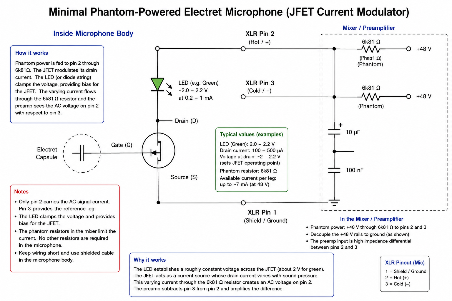
That doesn't work but this might (just a point to be careful with ChatGPT!)
This is what I'm thinking of - it's the same idea but uses the P48 power. It's pretty hard to break P48 because the currents are severely limited. And I should say this is a hypothetical hack! 🙂
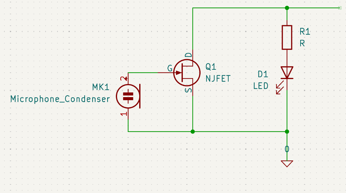
Take everything I say with a pinch of salt, I might be wrong and it's a very *expensive* way to learn!
Posted : 14/07/2026 12:23 pm
So I'm ordering the aforementioned circuit board, Songbird Michelle 3.5 from JLCPCB. This is my first time ordering something from them--it's my first time ordering any printed circuit board--so I'm quite out of my depth here. I ran into some things that brought up questions, and in order not to waste money, I thought I'd ask about them here. This question is mainly directed at @marcdraco but any help is welcome here. Here are the steps I went through (I also have a full screen recording of everything I did in case anyone wants it):
1. Uploaded .zip file.
2. Changed stackup to one listed here.
3. Changed "Impedance Control" from "No Requirement" to "+-10% (+-5 OHMs if value is less than or equal to 50 OHMs)", which was the only other option. This immediately jacked the price up about $33.
4. I'm not sure if the "Confirm Production File" setting needs to be selected as yes, especially as it adds an extra dollar to the price, but it was set to yes as default, so I left it.
5. I set PCB Assembly to "Assembly cost starting from $0 with coupon".
6. I changed the PCBA Quantity to 2 instead of 5, then clicked NEXT.
7. It took me to an image preview of the circuit board, and I clicked NEXT again.
8. It took me to a page with a "Add BOM file" upload field and a "Add CPL file" upload field. I stuck the bom.csv file in the BOM field, and the positions.csv file in the CPL field.
9. Weirdly it gave me an error when I clicked "Process BOM & CPL". It said "The below parts won't be assembled due to data missing. TP1, TP3, J1, TP2, TP4, J401, TP7, TP6, TP8, J405, J402 designators don't exist in the BOM file". I think this is not supposed to happen...? I clicked continue anyway.
10. On the next page, at the very bottom of the BOM list, in a row labeled "R410,R420" it says 4 shortfall. Apparently there aren't any of these parts left in stock. I clicked next to see what would happen here, but I was pretty sure at this point something's gone wrong.
11. I ended at the Quote & Order page, where it listed Charge Details: "PCB Price: $40.88", "Economic PCBA Price: $63.58", "TOTAL PRICE: $104.46".
My first question is, was the Impedance Control setting in Step 3 the correct one? Second question, is the error in step 9 expected? Third question, should I bother waiting for them to restock in Step 10, or is it possible to choose a different part? Last question, why the bloody hell is it so expensive? I thought the price of each board was ~$30, and I would have to pay ~$60 for two of them. Is this assumption incorrect, or did I do something wrong during the ordering process? Does it have something to do with the number of Extended components?
Again, thanks for helping a beginner 😀 😓
My worktable is a site of frequent detonations. Please knock so I don't start a Lithium fire when you startle me.
Posted : 15/07/2026 10:03 pm
Hi @imp-inventor, I probably need to amend the instructions further up the thread to include the TP stuff. TP just means test-point and JP is jumper. They're not fitted by JLC due to cost considerations.
The main "gotcha" by the look of it was the impedance control
Board "stackup" is JLC04161H7268 - 4 layer, impedance controlled. That's a no-cost extra but it's NOT an option. The USB needs an impedance control or it won't work with this design.
You can't just pick a random stack (and some of them are mighty expensive) - and JLC is weirdly complicated.
This is new since I designed the board. It just means that JLC will do the work I already did for you. But since I did it, you don't need to. 😉
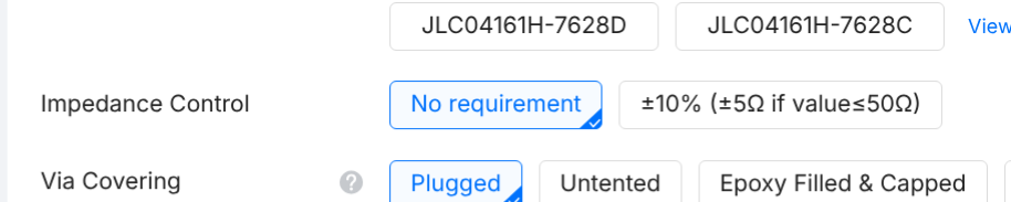
Without going into a huge song and dance, at USB frequencies, we're dealing with radio frequency design and that means the designer has to adjust a the width and (usually spacing) of the USB data pair from the point where it enters at the plug to where it is terminated at the IC. It's quite the mathematical dance to achieve something we all take for granted.
TL;DR: Leave ths option alone. Select the correct board as shown and you're good.
The "shortfall" in the BOM is a it's a useful one to look at how to fix it (because this WILL happen from time to time).
Each part has a bunch of specs like "perfect" electrical value and then a bunch of assumptions where it will do what it says on the tin,
For a board like Songbird you can assume that everything is operating at 6.3 volts or better. I put as much headroom in as necessary without being "weird" and some resistors go as high as 75 V but that isn't an issue.
What you have to watch out for with passives here is the size. The two pin everyday parts come in 0402, 0603, 0805, 1206 (and a lot of other sizes, but those are the "big four" currently).
Now this is where things get ... quirky. Not all resistors are created equally.
Two major types here are thick film and thin film.
- Thick film = everyday workhorse. Cheap.
- Thin film. = specialist low noise work. Costly (sometimes exceptionally so).
This is where one choice you can make as the assembler that I can't make for you without forcing your hand, so to speak. These four resistors (2 x 2k2 and 2 x 100 R) are the input pair and this allows you to over-ride "my" values with your own.
Most of you will want the BASIC type (what matters is the size 0603) and the value (2k2 and 100 ohms).
This is different from the setup Matt used and allows you to decide how you want the input stage to function (balanced or Common Source) and (this is another bit I left out) JFET operating current.
JFETs are odd fish - and the operate better (or worse) at specific currents and voltages - and you HAVE to trim them to do that. The 2N4416 works "better" at higher voltages than we have available. So these values can be adjusted at manufacture to match the JFET you have (if known) or the "impedance" if you only have the schematic from the mic supplier.
The other thing you can do here is replace the thick film "BASIC" set with something from the more exotic from the thin film "Extended" set. I don't have to run the numbers to guess how much difference thin film will make with a 10-12 dB boost provided at that stage. This is, as you might guess an advanced feature but as "Michelle" is designed for experimentation OR as a stand alone board for experimentation is with you.
When I did my own I just used the standard "thick film" type and the noise is all-but imperceptible - even in a no-signal condition with the gain shoved way up.
@wecan has one of the beta boards if he's still with us (assuming I didn't blow up his machine!) JK. 😉
Take everything I say with a pinch of salt, I might be wrong and it's a very *expensive* way to learn!
Posted : 16/07/2026 6:54 am
Muzammil17 reacted
@marcdraco I did think the impedance thing was weird...thanks for setting that straight. However, I've also found some other weird things that I thought I'd ask about before clicking the final button, and I got some screenshots:
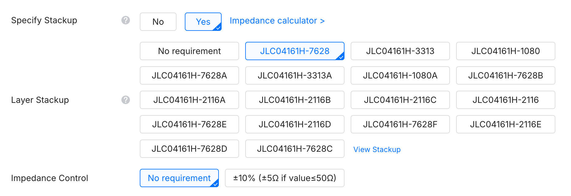
For this first one, while uploading the design and changing the settings, I noticed the stackup isn't quite the one you listed. The one I selected--JLC04161H7628--is the closest I could get to the one listed in your post, but I only realized it actually wasn't the same just now. Did you make a typo or is something else happening?
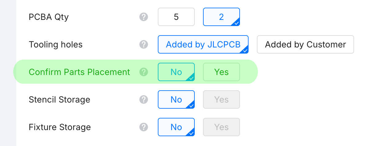
This second one I'm just asking about because I saw it in a video--is the highlighted setting necessary? It sounds important when you look at the description of the setting but you didn't mention it, and I assume you haven't made any polarity mistakes in the circuitry.
You mentioned the JFET. I have the 2N4416, and seeing as it would probably be easier to change the JFET than the preamp circuitry, do you have any suggestions for a replacement JFET?
Lastly, I suppose the missing items are back in stock now 🤣 Everything seemed to be in order with nothing missing when I went through the upload process today.
My worktable is a site of frequent detonations. Please knock so I don't start a Lithium fire when you startle me.
Posted : 16/07/2026 1:10 pm

Hi!
I've been following this forum for a while, and @marcdraco the work you have been putting on songbird michelle is amazing, I'm very excited and can't wait to try it out!
I'd love to build it for myself and my brothers, as we tend to do some LAN quite a lot and frankly I'm tired of our bad mic and hearing each others talking in reverb 😓
Unfortunately while I've done my share of hardware DIY, I'm more of a software guy, and this kind of project is way out of my knowledge area, so even ordering out parts on jlcpb or other websites is very confusing to me, and given the price I saw on my try, I would very much love not to mess up the order 😆
So my questions are the following:
- Is there any way for you to post some screenshots of the entire PCB spec and assembly configuration so that I can simply follow and I do not mess up? Just like @imp-inventor, I don't see stackup JLC04161H7268 in the list for instance, and will take no chances haha.
- You mentioned any good and cheap cardioid electret would be enough - do you have any brand or recommendation for a beginner that did not know any of those words prior to your post? I was planning on buying the JLI 25555 like Matt did in its video, but your recent comment about JLI not manufacturing any compatible capsule makes me second guess myself.
- I plan to design my own 3D printed enclosure, which is something I'm more familiar. Should I add some kind of fabric inside (or any other material), to mimic a pop filter, and if so, what kind?
- Is there any gotcha I should be warned about, or it should just be a quick setup process (solder the capsule, plug the mic, done) ?
thank you for your time, and again for your work!
Have a great day
This post was modified 2 months ago by nheuillet
Posted : 09/08/2026 6:45 pm
Hi there, sorry I've not been around for a few days (daughter on holibobs, daddy looking after the cats). They're still away but my own cat decided at 4.20ish (am) that I'd had quite enough sleep and that was that. 😉
- Is there any way for you to post some screenshots of the entire PCB spec and assembly configuration so that I can simply follow and I do not mess up? Just like @imp-inventor, I don't see stackup JLC04161H7268 in the list for instance, and will take no chances haha.
Sorry, I think a wheel came off there, but you've dropped in at a very good time, as I'm just prodding @imp-inventor for any final mods he fancied.
There are a couple of points I noticed in the final "beta" run that I figured I could have done better. This is the thing with developing anything but it gets to the point where you have to say, OK, that's enough... and this has been quite expensive due to errors from CMI datasheets, and such. :/
While not popular with some folk (and understand why) I'm turning to AI to help next time.
Why? The thing I missed wasn't in the main datasheet, it was lurking in a later addendum that wasn't entirely obvious (and wasn't, crucially, available through JLC).
I need something to hunt through documents and find things like that, that are so incredibly easy too miss. Or misunderstand. So I'm writing one.
It's not ready to scan websites or PDF (yet) but it recently chomped through the entire Odessy in under a minute so it's coming along. Public release will be up as soon as I get the fist 0.1 release finished. It's written in Go (which is a bit like C for those unfamiliar) with a more robust design than C but less of the complexity of C++. I love the new way of including stuff... Chef's kiss guys! Most people will skip this bit (because "software") but Ragamuffin is extensible and it's all interfaced - no complex faff, just JSON in/out. So pick you poison and write your own extensions! HMU if you want to know more.
- You mentioned any good and cheap cardioid electret would be enough - do you have any brand or recommendation for a beginner that did not know any of those words prior to your post? I was planning on buying the JLI 25555 like Matt did in its video, but your recent comment about JLI not manufacturing any compatible capsule makes me second guess myself.
Michelle will work with the existing capsule per Matt's original design. Matt added a JFET and constructed (in effect) what amounted to an electret capsule as the brass head assembly. Quite inspired really. Seems blinding obvious when you SEE it but then you've seen it, if you get my drift. Sorry. It's only 6am and I'm only two Lungos in. 😉 It's a thing, honestly.
The only thing I would change is that JFET. It's a fine device but requires a fair bit of "oomph" to get it going. This is fine when you're playing with a 20-30 V supply, not so much so with the 1v8 that Michelle produces.
One of the JFETs designed for this sort of application (there are a few left like the 2SK208 series) that are far better at lower voltages.
In fact the capsule is a good choice - for general use (and exceptional quality).
Diaphragm size is key. The larger the capsule, the less sensitive it is but conversely, the lower its frequency response will be. It's to do with the physics - the mass and elasticity of the thing itself as I recall). 25mm is a compromise between a vocal mic and something for lower end stuff. It's very much horses for courses and no one design fits all.
The thing is, most of us can't tell the difference... seriously. We can measure it - but even a cheap nasty, "free with your crunchy cereal" type of thing will give the JLI2555 a good run for its money. This is counter-intuitive but we're not comparing like for like.
The JLI has a very well balanced but LARGE diaphragm. This sort of thing is expensive compared to the much smaller (and likely thinner) ones that the "cheap" ones get away with.
Put a cheap 25mm against the JLI and it's like chalk and cheese... and I mean it's truly dire how bad the cheap one is vs. the decent one. The cost, of course, reflects that.
- I plan to design my own 3D printed enclosure, which is something I'm more familiar. Should I add some kind of fabric inside (or any other material), to mimic a pop filter, and if so, what kind?
And if you're not planning on screening your case, the JLI won't work. It absolutely MUST be shielded or you won't hear a thing (at least nothing useful).
- Is there any gotcha I should be warned about, or it should just be a quick setup process (solder the capsule, plug the mic, done) ?
Not really. It's not for *absolute* beginners but it's easier than the original Vero design (PCBs tend to be that way) but it's still hobbyist stuff. You're expected to be able to to some of this without having someone hold your hand. Honestly, as it's Open Source I wish someone like Sparkfun would sell the kits but I suspect the calculus doesn't work out too well due to the niche nature.
But plug and go?
Absolutely.
It's designed for compact electrets as I've said but that's a JFET issue mostly. The gain (when you get it) is fixed but it can be made variable per Matt's original although the resistor chain values are different since I used a better (!) input amp than the original.
Take everything I say with a pinch of salt, I might be wrong and it's a very *expensive* way to learn!
Posted : 11/08/2026 5:23 am
@marcdraco Thanks for you answer! No worries at all, real life is more important than the internet.
They're still away but my own cat decided at 4.20ish (am) that I'd had quite enough sleep and that was that. 😉
My own cat decided 5.30 in the morning every single day was the only time he would get cuddly, and frankly a bit too playful with his claws so I definitely know the feeling 😵
Sorry, I think a wheel came off there, but you've dropped in at a very good time, as I'm just prodding @imp-inventor for any final mods he fancied.
There are a couple of points I noticed in the final "beta" run that I figured I could have done better. This is the thing with developing anything but it gets to the point where you have to say, OK, that's enough... and this has been quite expensive due to errors from CMI datasheets, and such. :/
Fair enough ! I can wait for those prodding then, you should never rush greatness. 😉
Your tool does sound quite interesting! I can definitely relate to the hunting part, it is always a pain to scrap through half the internet only to miss that one sentence buried on page 79 of an obscure spec. I love Go, I think it's a great compromise of being able to solve most use case with a much simpler learning curve and environment compared to most languages. I wish it wasn't so simple sometimes though ( I miss Enums mostly )
Michelle will work with the existing capsule per Matt's original design. Matt added a JFET and constructed (in effect) what amounted to an electret capsule as the brass head assembly. Quite inspired really. Seems blinding obvious when you SEE it but then you've seen it, if you get my drift. Sorry. It's only 6am and I'm only two Lungos in. 😉 It's a thing, honestly.
I just rewatched the video after your comment, and it finally clicked on me why the brass head is not simply for decoration! I am slowly getting a mental image of the project, but it's not there yet haha. The audio domain is truly fascinating.
Yeah in that case I'll have to copy Matt's capsule design entirely (minus the whole arm attachment thing I guess). I am also interested in variable gain, but honestly I'll worry about that later. This is such an exciting DIY. I can't wait to experiment on it!
Posted : 11/08/2026 9:29 pm
I would definitely use Matt's capsule design. (I've done some boards for heads but adds to the cost because JLC won't let me bundle them *and god knows, I've tried. 😉
Variable gain is very much as Matt's original (no point chucking away a perfectly good design). The only thing is - and this applies to both the original and the new ones.
The gain resistors are in the signal path - it's fairly low impedance at this point, but it wouldn't hurt to screen them with a "blind" shield that is grounded at one end only. I haven't tried the new INA with this but it's a similar design to the THAT internally.
Take everything I say with a pinch of salt, I might be wrong and it's a very *expensive* way to learn!
Posted : 12/08/2026 10:52 am
nheuillet reacted

I am going to get the brass pieces custom-manufactured. What are the exact dimensions of each? Length, width, type (hollow or solid)
Posted : 20/08/2026 12:29 pm
Where do I start as a complete beginner?
I watched the YouTube video and want to build it, but I saw people talking about revisions on this forum..?
Which diagram should I buy the components for? I've never touched a breadboard or built something similar before.
Posted : 20/08/2026 5:59 pm
@lopya I don't think we ever produced a "drawing" template.
However the ring (which is the tricky bit) has to mount around a JLI2555 (25mm or 1") formatr LDC (large diaphragm condensor).
The base drawings from JLI are the canonical reference.
Take everything I say with a pinch of salt, I might be wrong and it's a very *expensive* way to learn!
Posted : 21/08/2026 2:06 pm
@lopya If you're new to electronics, the original design is going to reduce you to tears. Really. It's a beautiful design but like a Lotus racing car, it's stripped to the bone.
Which means it's very easy to break something.
Even "Alpha" which was the best I could do before finally throwing the towel in (Alpha came later) and working on a new design from the ground up that covered all the bases Matt couldn't.
And then some genius decided it would be a good idea to start slapping tariffs on anything and the cost of Songbird "Michelle" rocketed beyond what I would consider "reasonable".
If your budget can wear it (if you're in the United States @imp_inventor has a better idea than I do) but we're getting pummelled in the EU too.
What a mess.
Michelle is as near bullet-proof as you can get while delivering very, very good specification right into the USB port of your PC.
If you want some soldering experience, the Alpha is "passable" (about on a par with the original *some* protection for the downstream parts but not a huge amount). It's a lot cheaper as you only need to order 5 boards from JLC PCB (simple and quite cost effective).
What costs the money is we get slapped with ALL the tax and ALL the duty because (despite this not being a product as such) it's sufficient to trigger it.
Take everything I say with a pinch of salt, I might be wrong and it's a very *expensive* way to learn!
Posted : 21/08/2026 2:17 pm
@lopya If you're new to electronics, the original design is going to reduce you to tears. Really. It's a beautiful design but like a Lotus racing car, it's stripped to the bone.
Which means it's very easy to break something.
Even "Alpha" which was the best I could do before finally throwing the towel in (Alpha came later) and working on a new design from the ground up that covered all the bases Matt couldn't.
And then some genius decided it would be a good idea to start slapping tariffs on anything and the cost of Songbird "Michelle" rocketed beyond what I would consider "reasonable".
If your budget can wear it (if you're in the United States @imp_inventor has a better idea than I do) but we're getting pummelled in the EU too.
What a mess.
Michelle is as near bullet-proof as you can get while delivering very, very good specification right into the USB port of your PC.
If you want some soldering experience, the Alpha is "passable" (about on a par with the original *some* protection for the downstream parts but not a huge amount). It's a lot cheaper as you only need to order 5 boards from JLC PCB (simple and quite cost effective).
What costs the money is we get slapped with ALL the tax and ALL the duty because (despite this not being a product as such) it's sufficient to trigger it.
Take everything I say with a pinch of salt, I might be wrong and it's a very *expensive* way to learn!
Posted : 21/08/2026 2:18 pm
@marcdraco Why not source the components or PCBs from China? I'm planning on purchasing the components for "Alpha" or Songbird "Michelle" from there. (By the way, which one should I assemble on a breadboard like in the original video?) I know some people got loud static issues and I definitely want to avoid that..
I learned my way around Chinese e-commerce and I purchase identical products from there for 1/4 of the price. Exact same stuff but without the EU tax and their absurd delivery fees.
Posted : 21/08/2026 6:54 pm
Alpha is a plain board to to the US it's just a few $ for a pack of 5. It's a better layout (because it's on a PCB rather than a piece of stripboard, which trust me, is horrible to work with if you're new to this. Ironic because it was aimed at beginners and I grew up using the stuff; getting a lot wrong as a result. 😉
If you're happy with China, I would recommend the Songbird, simply because it's much simpler to build (there are a couple of minor "gotchas" if you want to prod but nothing that should "kill" it unless it's really abused.
Strictly speaking, it's still in "beta" but it blows the original away in every metric but due to some annoying constraints on parts, the final solution is a combination of "works out of the box", given pretty much any electret capsule, you should be able to get it running in minutes.
There's a LOT going on but broadly:
- A very high quality input stage (which you *can* improve using better parts if you need) which feeds into a very high quality digitizer which converts the signal from analogue audio. At least as good as or better than the THAT under similar conditions.
- A very good quality TI digitizer (32 bit!) delivering I2S via an external clock. It the I2S lines are available as outputs.
- A USB interface from CMI - the CMI108B
- Supporting that are some quite exotic power supply components delivering +5 V and -5 V for the analogue parts.
- Serialised 1v8 output to the electret.
- Single or balanced inputs.
The priority is on signal conditioning before it even hits the digital electronics and it's pure from there all the way into your computer. The CM108B (an "ok" headset mic and amp) is only there to provide a convenient (cost effective AND practical) I2S -> USB interface (bridge). I've designed the hardware to bypass all of that junk and operate this thing at fully 32bit and 192KHz - but (drum roll) I'm just not a good enough programmer these days to take on the STM32 development kit. It's good, very very good, but there's not enough scaffolding in there for me to work with.
(It's an STM32F7... setup but someone needs to be able to write the I2S -> USB bridge and while the hardware is more than capable (perhaps due to the difficulty) no one has developed a solid bridge for Open Source Hardware use.I think it's probably too niche.
All the design files are further up the thread - although you'll need KiCAD (9+) which is a free download to read through them and laugh at my amusing abusive notes that I write myself at 3am when I'm holding my eyelids open with sticks and the larks are thinking about getting up.
Take everything I say with a pinch of salt, I might be wrong and it's a very *expensive* way to learn!
Posted : 22/08/2026 3:38 am

Just found the original video and immediately went diving into this forum to see if there's been development in the last four years. Super cool to see Marcdraco putting so much effort into the upgraded version. I'm subscribed to the thread to keep up with progress and I'll hopefully have the time and money to commit to building a v3.5 or v4 later this year if it's ready by then.
Posted : 03/09/2026 9:40 pm
@avieatrix It's ready but the cost of parts from China (due to political problems) has made it quite costly.
3.5 is fully functional but as with any "beta" there are things I could have done better, there's also the question of if I should do a version without the CM108B (which is the "USB bridge" even though it's sold as an A/D).
@imp_inventor and I have been discussing to see what else would be useful and if you have any "requests" provided they're achievable, I'll include them.
Take everything I say with a pinch of salt, I might be wrong and it's a very *expensive* way to learn!
Posted : 04/09/2026 7:15 am
@avieatrix It's ready but the cost of parts from China (due to political problems) has made it quite costly.
3.5 is fully functional but as with any "beta" there are things I could have done better, there's also the question of if I should do a version without the CM108B (which is the "USB bridge" even though it's sold as an A/D).
@imp_inventor and I have been discussing to see what else would be useful and if you have any "requests" provided they're achievable, I'll include them.
Take everything I say with a pinch of salt, I might be wrong and it's a very *expensive* way to learn!
Posted : 04/09/2026 7:24 am