Hi @marcdraco
Thank you for the detailed explanation. Note also that I am a physicist. Yes, we had two subjects on microelectronics, one dealing with the quantum principles of semiconductors and the other with the design of basic amplifiers and logic circuits, so your text is for me at best... fuzzy.
Anyway, I started building this microphone because I wanted to build a cheap microphone to measure the speed of small motors with my Raspberry Pi. As you can see below, I can reliably determine frequencies down to about 20 Hz, but below that frequency the motor revolutions are so quiet and the microphone noise is so great that it no longer works.
To improve the situation, I could try to do two things:
- Get a larger condenser microphone module. Physically, larger diaphragms should capture lower frequencies better; currently I am using a 25mm capsule I got at AliExpress for peanuts, but there are also larger 34mm capsules for, say, $20.
- Have an amplifier design that allows the gain to be changed electronically, that is to make a feedback loop with the Raspberry Pi where the gain is increased for quieter sounds at slower revolutions - I was going to use a digital potentiometer with Matt's design, but digital potentiometers only work up to 5V, so the design should probably be completely different.
- Have an amplifier design that is more suitable for lower frequencies.
These three points are my current interests, if you have any suggestions along these lines I am all ears.
@pygmalion Sure... now here's a funny story, I'm currently writing my second screenplay and it's based on the current debate about us being information on the edge of a black hole and all that jazz. I won't lie, it's all way over my head, but it's making for a cracking thriller!
Anyway -- there's a way to capture low frequencies with a small electret using (I think) the surface effect. I agree that a larger diaphragm should be able to capture lower frequencies but there's something (and the explanation escapes me, but I read it recently) to suggest that's not necessarily the case.
Electronically we also need to be aware of the roll-off of the components used. Rod Elliot (of ESP) makes a great point that we should aim for a roll-off 5x LOWER than we want to capture in order to get the audio frequencies we want. I wasn't entirely sure what he meant by 5x - but I'd guess he means for a 20Hz capture limit, we'd roll the 3dB point to 4Hz. It makes good sense.
But even SDC mics can capture audio even into the subsonic using (I think) a SAW wave. Again, it's been a very long time since I did any work in this area, but I recall some army chap had erected a huge board that he used to capture the sounds coming from an artillery range. I wish I could remember the link. It might be on Seigfried Linkwitz's site though, there's LOT over there. https://www.linkwitzlab.com/sys_test.htm#Mic
The guy was a genius and led me to the WM61A which I've used in many designs although I've moved to the Primo capsules now as they offer far better performance than the Panasonic did and it's sadly no longer made.
I've had a quick look at that army test rig isn't there... there's something to so with the way that a large baffle captures sound in much the same way that the proximity effect works (you know when you talk really close to a mic and the bass response goes through the roof). The gotcha (there's always a gotcha) as you'll know is the wavelength of sound at low frequencies in air is... long - about 17 meters (!) at 20Hz for example. I experimented with shorter waveguides (similar to the ones radio hams use but with wooden baffles rather than wire) but without much luck.
But I digress.
When it comes to the size of the diaphragm I'm unconvinced it makes that much difference - although the large ones do look nicer. But consider the MEMS mics in your mobile phone (bloody things are everywhere these days). They're quite capable of capturing respectably low frequencies and they're minuscule. MEMS is a fascinating development really - I've been tinkering with the accelerometers that use a MEMS spring in something about 1mm square.
https://www.cmlmicro.com/mems-microphones-why-is-digital-best/
(Good lord, I just read they date back to 1983 when I was still an apprentice!)
https://www.mouser.com/catalog/additional/Cirrus%20Logic_WAN0290_v1.0.pdf
Anyhoo - you'll see from that the Cirrus people have one that's -3 dB at 20Hz! So size isn't everything (Oh err, nudge-nudge, wink-wink sounds a bit rude).
For your experiments I'd recommend a simpler microphone - not a MEMs, they need flow soldering and often have a DAC CODEC on board now.
Micbooster has a great selection including ones where the internal FET isn't wired so you can set your own current to suit your needs. Clever that.
https://micbooster.com/22-primo-microphones
You'll see they also stock a VERY expensive FETless type (EM23) that makes me drool a bit... The circuit shown on the datasheet is a self-biasing FET type that should give pretty even output at reasonable levels too.
They also stock the JLI capsule Matt's used and some ones with FETs on board that run at 1.5V which is massively convenient because it saves all the fiddling around with FET biasing which is a nightmare. Many designs (even professional ones) rely on trimmers to set the current because of the manufacturing spread. There are self-biasing systems (I checked my design books and there are more than a dozen!) but few offer great performance unless you get one (or two) monolithic matched pair FETs.
I'm getting off-topic here and the cat wants to go to bed so I'll try to be quick!
It's not that the subsonics are quiet, it's the buggers are difficult to capture - but they will have SOME effect. (Forgive my over explanation but I expect other people without our experience could read this).
I would imagine that a ribbon mic would be more suitable for low frequencies but they are perilously fragile and the tiniest gust of wind will snap the motor. I've "suggested" to Matt that he might use his amazing construction and design skills to make a motor design that allows us to drop a ribbon into place between two super magnets and then can be adjusted until the magnets sit just uM away from the ribbon. This will give us the best sensitivity but it's totally impractical for all but the most gifted to drop a ribbon into such a tight space. If it hits the magnets anywhere, the sound is distorted and that's useless.
I've designed a plastic (3D printed) corrugator and razor cutter for cutting and shaping the ribbon but that's the limit of my skill.
I can cut and corrugate ribbons all day long but can I heck as like get them into place without destroying them.
Even if I could, there's the problem of impedance. The impedance of the ribbon is in the order of milli-ohms so it needs a transformer to bring it up to the sort of level where transistors can be used.
Which rather leaves us with condensers but that's OK because a decent condenser mic offers the best all-round performance. (I've seen optical mics but I don't have enough experience to know where you'd get one, let alone what it would cost!)
So you have your mic and you want a circuit to amplify based on a voltage - you're in luck!
The one I've presented above (I should be able to check it in a day or so, production assistant willing) will work as low as 4V I believe, that's a start if you really want to use the large capsule route. Personally (and this is my preference) I like SDCs because they are lower in cost and produced in such numbers that the quality is good for the money.
Less faff too because they don't tend to pick up all manner of interference because the FET is inherently shielded. They work from 1.5 to -9v without issue too. Higher supply voltages give you a better signal level without any real increase in background noise. I doubted that but I tried it and sure enough, they're surprisingly pleasant to use!
ELECTRONIC VOLUME
You won't be surprised to learn that FETs make really sweet little electronic volume controls. There should be loads of examples online. N-channel is a bit of a PITA because you have to bias the gate more negatively than the source to reduce the volume. Linearity is a problem to if you need accuracy. I've seen digital resistor ladders that use a combination of MOSFET switches and a resistor ladder for super-duper-accurate level control. I believe (haven't checked) they are available in log and linear progression too. I'll certainly look these out if you need a hand.
LOW-FREQUENCY DESIGN
That tends to be the preserve of DC-coupled amps and (drum-roll please) that's exactly what Op Amps are great for!
I don't know your budget but a simple mic like a JLI-2950 or EM258 (both with internal FETs) is going to be a hell of a sight easier to use.
Op Amps work all the way to DC so the only thing we need to do is design a simple (say) 10x inverting amplifier with say 10K input impedance and a -3dB point down in the single digits. That shouldn't be too difficult but the cat is really getting restless as it's an hour past cuddle time.
An NE5535 (stereo, audio op amp) should do that trick nicely. It's low THD and pretty easy to use - you can even bias it to run on a single supply.
Let me know if this makes sufficient sense. I'll make a point of trying to find the part numbers when this animal takes a nap! I assume you're familiar with the I2C protocol? That's likely the easiest way to control these chips although it might be easier to use a small Arduino to do the control unless you're a bit handy with Pi programming (I'm OK, but I work better without an OS getting in the way as I like to hit the metal as it were).
Marc
UPDATE: I did a quick check and you can get a 256 stage, 10K digital potentiometer for a couple of quid. Probably better to get one on a breakout board though. Through-hole ones are available but (as you might expect) the SMD versions are cheaper.
I would expect it's possible to use such a device in the feedback loop of an everyday op amp and hey-presto you're cooking on gas!
Op Amps are (for the most part) ridiculously easy to use like this and modern ones are almost indestructible with their outputs shutting down in a short circuit condition, etc. So no need for an FET.
I have some sample circuits for things like compressors that use FETs as volume controls but why bother when there is a nice Digital solution!
Ohh... and here's an eyewateringly expensive SUB-BASS professional mic. Look at the size of that capsule!
https://www.thomann.de/gb/neumann_ma_1.htm
Take everything I say with a pinch of salt, I might be wrong and it's a very *expensive* way to learn!
Well slather me in honey and call me "Sweetie" - it works.
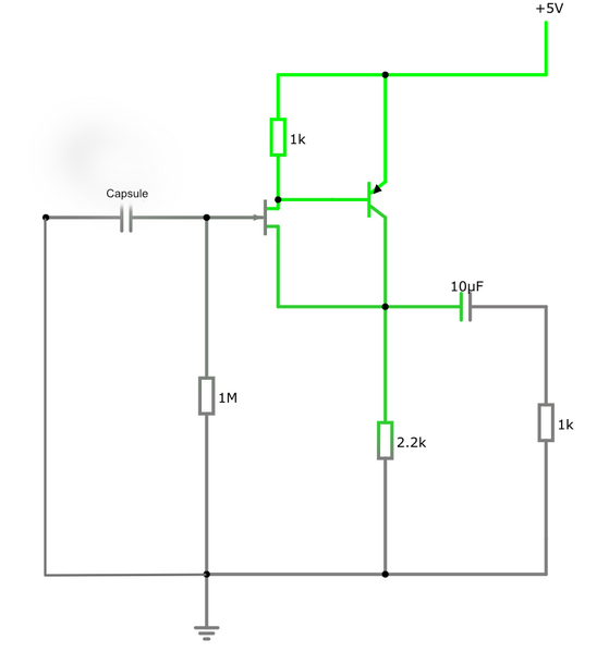
I know it worked in the sim, but sims are ... well, simulations and they often get it wrong. I've repeated the circuit here for clarity, the output 1K resistor represents the load (you don't need to put it in the circuit). It's such a tiny circuit you can probably get the whole thing wired point to point (if you're careful) and mount it right next to the capsule so it can all be shielded together. If you wanted to improve the linearity beyond this point you could use a current sink in place of the 2K resistor. I would imagine that's what Rode did in the NT1000.
I've hooked it up to the XLR on the C100 and it hums like a good 'un. This is really annoying but not surprising since my place has mains running all over the place and I haven't built a screen per Matt's design.
I can't find the input impedance for these XLRs but it's something around 1K5 (or perhaps a lot less) and this circuit drives it without breaking a sweat. If you wanted line level (1v p-to-p I think) it would need further amplification. This rolls off at about 15Hz with the values shown.
Gotta love Doug Ford for showing this, it's not featured in any of my design books but apart from working well on a single supply (I'm using a 9V PP3/6LR61).
There's no question this will drive the microphone input on a PC. I'm going to need to find an old USB cable to try it on 5V though - the simulator suggests it should work all the way down to 4V, but the FET is getting pushed a bit by that point.
Apart from being simple and cheap, the beauty of this design is that its performance is driven by bootstrapping the source which reduces distortion to levels well below what we can hear. I won't lie, you WILL get greatly improved performance from an OPA1642 because it's a beautiful design (reminds me of the LM10 which is quite old now, but it was jaw-dropping when it appeared and we were all worshipping at the altar of the great Operational Amplifier. ( https://en.wikipedia.org/wiki/Bob_Widlar )
Joking aside, Bob was truly one of the greats and he was taken far, far too soon. Even today, that's still quite a smart little chip. The Wikipedia page has some great information on him if you're interested. It's quite amusing to look at the 1967 Widlar current source and think, "we use that all the time" without giving it a second thought. Poor guy probably drank himself into an early grave - I suspect that's the real issue for true geniuses. Few seem to live extended lives (Dr. Brian May is a wonderful exception to that rule - long may he reign supreme.)
Hopefully, this little circuit will help someone who doesn't want to go to the expense of the THAT1541 and the voltage doubler. It will still need a decent screen as it will amplify every passing bit of EMF but that's nothing new for this sort of thing. You could probably put a tuned circuit on it, add a diode detector and you could likely listen in to most of the AM bands.
To your problem @pygmalion I would suggest you stick with a decent quality SDC as I've described above.
I'm happy to design something to help with the subsonics/infrasound you're trying to detect but the problem with filtering is going to jigger the results. I think a Butterworth setup which has a gentle roll-off and little ripple in the passband would be the most suitable. A two-pole Salen-Key design is dead easy with a single op-amp.
Anyway, hit me up if I can be any more help!
Take everything I say with a pinch of salt, I might be wrong and it's a very *expensive* way to learn!
Hello Marc,
Anyway -- there's a way to capture low frequencies with a small electret using (I think) the surface effect. I agree that a larger diaphragm should be able to capture lower frequencies but there's something (and the explanation escapes me, but I read it recently) to suggest that's not necessarily the case.
Electronically we also need to be aware of the roll-off of the components used. Rod Elliot (of ESP) makes a great point that we should aim for a roll-off 5x LOWER than we want to capture in order to get the audio frequencies we want. I wasn't entirely sure what he meant by 5x - but I'd guess he means for a 20Hz capture limit, we'd roll the 3dB point to 4Hz. It makes good sense.
But even SDC mics can capture audio even into the subsonic using (I think) a SAW wave. Again, it's been a very long time since I did any work in this area, but I recall some army chap had erected a huge board that he used to capture the sounds coming from an artillery range. I wish I could remember the link. It might be on Seigfried Linkwitz's site though, there's LOT over there. https://www.linkwitzlab.com/sys_test.htm#Mic
(snip)
When it comes to the size of the diaphragm I'm unconvinced it makes that much difference - although the large ones do look nicer. But consider the MEMS mics in your mobile phone (bloody things are everywhere these days). They're quite capable of capturing respectably low frequencies and they're minuscule. MEMS is a fascinating development really - I've been tinkering with the accelerometers that use a MEMS spring in something about 1mm square.
https://www.cmlmicro.com/mems-microphones-why-is-digital-best/
(Good lord, I just read they date back to 1983 when I was still an apprentice!)
https://www.mouser.com/catalog/additional/Cirrus%20Logic_WAN0290_v1.0.pdf
Anyhoo - you'll see from that the Cirrus people have one that's -3 dB at 20Hz! So size isn't everything (Oh err, nudge-nudge, wink-wink sounds a bit rude).
For your experiments I'd recommend a simpler microphone - not a MEMs, they need flow soldering and often have a DAC CODEC on board now.
Micbooster has a great selection including ones where the internal FET isn't wired so you can set your own current to suit your needs. Clever that.
https://micbooster.com/22-primo-microphones
You'll see they also stock a VERY expensive FETless type (EM23) that makes me drool a bit... The circuit shown on the datasheet is a self-biasing FET type that should give pretty even output at reasonable levels too.
I actually experimented with electrolets a few years ago. I bought simple cheap modules with MAX4466 and MAX9814 from AliExpress ( https://www.aliexpress.com/item/32660519341.html). The problem is sampling, because these modules have a simple voltage as output. At that time I was a bit naïve and used different ADCs (MCP3424, ADS1115) but the result was poor.
Maybe I should connect the output of these module to an audio card instead, or maybe I should buy a pure electrolet and connect its output to Matt's amplifier. I am a bit clueless to these possibilities, but if you have a suggestion along these lines I can give it a try.
I have also been experimenting with MEMS. There are nice I2S MEMS modules on AliExpress ( https://www.aliexpress.com/item/4000045517597.html) and initial tests gave pretty good results, with 50Hz suppressed well. But the I2S support for the Raspberry Pi is ... horrible. It stopped working and I never managed to get it working again.
Unlike I2S, I2C works great and I work with it a lot. I even wrote a library for the MCP4728 and published it on GitHub because I use it to control the voltage of motors (I do a Raspberry Pi controlled voltage sweep).
SAW waves are easy to capture as they have a distinctive set of high harmonics (see Fourier Transform). Motors also have a few weaker higher harmonics and I use them to "guess" the fundamental frequency, even if the latter is hidden in the noise.
In conclusion, you have convinced me not to pursue the path of buying larger condenser microphones, as it probably would not make much of a difference anyway.
UPDATE: I did a quick check and you can get a 256 stage, 10K digital potentiometer for a couple of quid. Probably better to get one on a breakout board though. Through-hole ones are available but (as you might expect) the SMD versions are cheaper.
True, but I can not use them on Matt's amplifier because they are all limited to 5V.
I will not comment on the electronic part of your post because I understand next to nothing.
In summary, I currently have I2S MEMS, two electret modules with MAX4466 and MAX9814, a DIY condenser microphone, Matt's amplifier and an audio card. I can also buy a pure electret and other cheap stuff on AliExpress and build simple circuits. I have experience in using and programming Arduino and Raspberry Pi. If you have a good suggestion in this regard, I would love to try it out.
Marko
To your problem @pygmalion I would suggest you stick with a decent quality SDC as I've described above.
I'm happy to design something to help with the subsonics/infrasound you're trying to detect but the problem with filtering is going to jigger the results. I think a Butterworth setup which has a gentle roll-off and little ripple in the passband would be the most suitable. A two-pole Salen-Key design is dead easy with a single op-amp.
Anyway, hit me up if I can be any more help!
Marc, if I understand you correctly, the DIY SDC (small diaphragm capacitor) I built is the best option. Better than electrolet or MEMS...
If so, my main question would be whether it is possible to design a similar amplifier with electronically controlled gain. At lower speeds, the frequencies are smaller and the motors are quieter, so I would need to increase the gain as I decrease the motor voltage. Reducing the noise at lower frequencies would also be a good thing.
Marko
PS Maybe this is off-topic for this forum and we should choose another way of communication.
@pygmalion You could be right, while this is all high-impedance microphone and low-noise tech, your specific application really deserves a topic of its own so I'll open something up in a more suitable place on the forums. I'm happy for us to discuss this on DIY Perks as Matthew is obviously interested and others might be able to gain some insights from our discussions, particularly as I need to understand what your aims are. I'll keep the maths simple because I'm not great in that area myself. 🙂
Take everything I say with a pinch of salt, I might be wrong and it's a very *expensive* way to learn!
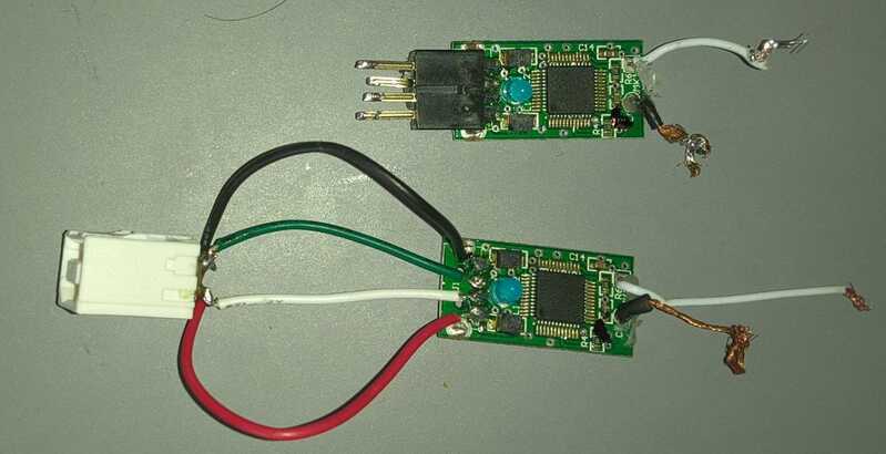
I'm using a behringer mic 2 usb audio interface and I can't for the love of god solder it to usb b port, i even tried soldering the usb cables directly to the behringer usb pins but it just wont work, if I plug it in directly it works fine tho, it's very annoying since they weren't all that cheap, did you guys run into similar problems with an usb audio interface?
Hmmmm. Well, I finally got the replacement op-amp. I was wondering why next day delivery took over a month, but I guess the payment failed because the Paypal window hung or something. I re-ordered, and it came...the next day. Anyways...still no joy. Next, I'm going to pull apart an old earbuds lead and wire an .MP3 player directly to the input of the A/D converter to see if it's the problem.
I think I'll also test the output from the circuit board. I assume the level will be enough do drive a powered speaker, since they'll run off a headphone output?
Barring a faulty component somewhere, I dunno what the problem could be.
Windows recognizes a "USB 2.0 microphone", but I think it's just recognizing the A/D converter. Though, mine also had a video input, so I dunno why it's recognizing it specifically as a mic unless the converter is just detecting that the audio part of it is connected to SOMETHING.
Maybe the voltage booster dealie is the problem. I've double and triple checked the circuit board, both for shorts between strips, and bad joints. (At least where I have access to the component lead on the top side of the board)
The only other thing that comes to mind is if the transistor is wired wrong. But I just used the link from the video. I wasn't sent a data sheet, and never checked the one on the site, but I dunno why they'd randomly change the pinout without changing the part number.
@axy_david Can you be a bit more detailed David? I can't follow exactly what the problem is.
Take everything I say with a pinch of salt, I might be wrong and it's a very *expensive* way to learn!
@ashleigh Hard to know for sure without having your board in front of me, but (and this is weird one) the circuit shown shouldn't work because there isn't a DC reverse biassing resistor from gate to ground. Obviously, it works for Matt but Doug Ford (Doug Ford Analog Designs) raised a similar question about the internal FETs on lucky-bag electrets that you find on eBay.
So that's the first thing to try (it won't hurt) - drop a 1M (bigger if you have it) resistor between Gate and Ground (0v) to see if that helps.
If you operate the capsule outside of Matt's lovely little head basket it should hum like a bunch of drunks on the way back from the pub - and about as tunefully too.
If it doesn't, there's something wrong with your circuit - but don't prod around too much with other devices or you risk breaking them too.
Check the power rails are energised correctly first and then check that you have the expected voltage drop on the THAT1512. I believe it's a standard layout so that means 30v from pin 4 to 7; 15v from pin 7 to ground and -15 from pin 4 to ground.
You should also see about 15V DC dropped across the 2k2 resistors in the power section and a small voltage dropped across the 100-ohm ones too.
There may be a very small DC voltage on pin 6 due to imperfections on the chip but that should be about it. I'll assume from what you said you don't have an oscilloscope handy.
Another thing you can try is putting your meter (you do have a meter?) onto its mA range (10 mA at least) and measuring the current from either the 2K2 to the drain OR the 2K2 from the source terminals while the GATE terminal is held at 0v. This won't break anything but it's a good way to tell if your FET is operating.
You can check the FET on the bench by carefully, and temporarily joining the source to the gate terminal and using a small voltage such as a 9v battery (or your 15v) to see if the current flows. You should see up to about 5-10 mA in that circuit too. This sounds like madness I know, but JFET current regulator diodes are literally made this way and even flat out with the channel wide open, these devices at a little like a resistor of a few k in value.
Let me know how you get on.
Take everything I say with a pinch of salt, I might be wrong and it's a very *expensive* way to learn!
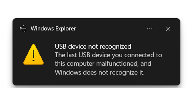
If I connect the pins directly into my laptop the thing works fine, however if I solder it directly to a USB wire, or a USB B port, it will say device not recognized.
@marcdraco Haven't had time to test everything you mentioned, but so far, I added a 1M resistor from gate to ground. Nothing.
I get 0 volts from pin 4 to 7 on the 1512, and 0 from 7 to ground. But the power rails seem fine - 15 volts either side and 30 from one side to the other. So I'm thinking I may have a bad joint or a dead cap somewhere perhaps.
So I think I'm just gonna check all the joints for continuity, then measure the voltage in a bunch of places. It's even possible that the op-amp isn't seated properly in the socket, I guess.
I guess I better check polarity of the power rails, too. I think I remember someone saying it was reversed on theirs, 'cus they got a fake off EBAY
Edit: Polarity is right. Also: I get 15v across both the 100r resistors, but nothing across the 2.2k's. I had initially wired one of the caps backwards, but I don't see that killing it. I'm starting to think I just have one bad solder joint somewhere
@ashleigh Yeah sounds like a dud joint somewhere - if both the main rails are dead, it's likely you have an issue with your ground and if the THAT 1512 isn't getting power nothing else is going to work.
A dead cap is unlikely out of the box. Reversing polarity does kill them but you'll usually get a warning like Magic Smoke.
You can check them with your meter on the resistance range - but make sure you discharge them (carefully, us a 10 - 100 R resistor). You'll see your meter might show a short for an instant but the impedance will rocket to effectively infinite in a fraction of a second. You have to do this out of circuit though. You can do it in-circuit with a device called a scope octopus, one of the best kept secrets of us old guys, but you need a scope to to that.
If you're working on strip board per Matt's design, be aware that the stuff is notorious for very tricky shorts caused by solder bridges so thin you need a magnifying glass and copper traces where you've cut the tracks too. This is why I prefer not to use it whenever possible.
Do keep me posted though.
Take everything I say with a pinch of salt, I might be wrong and it's a very *expensive* way to learn!
If I connect the pins directly into my laptop the thing works fine, however if I solder it directly to a USB wire, or a USB B port, it will say device not recognized.
B port? You do mean "A" port don't you? 'B' is the squarish one that goes in the back of a peripheral device such as a printer. The colour code varies from US to China though.
Two things come immediately to mind. One is the data lines are a balanced pair for noise isolation (just like the circuit in Matt's microphone) and should be a twisted pair, not just laid out on the desk like that. However, unless you've got a REALLY noisy environment, I doubt that's the issue, but you really should use an existing USB cable to do the hookup even if you have to buy one from the £1 shop and chop each end off. 😉
From memory, I believe that the USB senses a new device when it detects a load on the data lines (which produces a voltage drop on a the input that can be sensed by a MOSFET with its eyes closed). This suggests that either:
You've accidentally reversed the two data lines (I won't admit how many times I've done that... but it's more than once when I've been working inside a PC with one header socket per line...) or one of the data lines isn't connected at all.
Take everything I say with a pinch of salt, I might be wrong and it's a very *expensive* way to learn!
@marcdraco So, if I'm getting 15v in to ground on one side of each those two 100r resistors, but nothing from anywhere the other side of them, doesn't that suggest the resistors themselves are the problem? Maybe they both died because of the backwards cap? I'll have to check the bands, too, cus they may have been mislabelled
Edit. Yeah. Somehow the pack I'd labelled as 100 ohm, is full of 3.3M resistors. And they're dark blue, so I can't even see the bands without an extra light source
Edit. Yep. Now I feel kinda foolish. 🙂 Now the mic works, though the level is extremely low, but that could be because for now, I just soldered a 10k resistor in place of the gain control. I'll find something smaller and see how it goes
Edit. Seems to be working. I can'tcomment on the quality or noise level yet, cus I'm doing something different with the housing, so everything is currently out in the open with no shielding and I'm getting crazy buzzing. I don't need to check the pitch to know it's 50hz. I recognize it anywhere. Plus, everything is sitting on top of my PC tower, so... 😀
@marcdraco So, if I'm getting 15v in to ground on one side of each those two 100r resistors, but nothing from anywhere the other side of them, doesn't that suggest the resistors themselves are the problem? Maybe they both died because of the backwards cap? I'll have to check the bands, too, cus they may have been mislabelled
Edit. Yeah. Somehow the pack I'd labelled as 100 ohm, is full of 3.3M resistors. And they're dark blue, so I can't even see the bands without an extra light source
Ouch! Well that's probably it - 3.3M won't pass enough current to electrocute an amoeba.
I completely agree. This blue colour they're using these days doesn't have the contrast we got with the brown and yellow ones in my day. I still check every single resistor with a meter before I put it on the board. This is actually one more area where SMD is preferable.
When I was a kid I could read some of a circuit just looking at the resistor colour codes. (We were taught to but the tolerance band to the bottom or right of the PCB so we could read it at a glance. None of this "stand them on their end" stuff back them. Everything was flat on the board with legs bent to reduce strain.) At least most SMDs are marked with simple numbers so you can read those. Small caps aren't though, so they're a bind.
Take everything I say with a pinch of salt, I might be wrong and it's a very *expensive* way to learn!
@pygmalion MEMS that's it.
You can't hear the subsonic but that doesn't matter - one of these bad-boys would be simple and more accurate I would imagine.
You'd have to mount it to something physically connected to the motor of course. I could well imagine that any audible frequency it "hears" could be easily filtered out by the computer.
I also looks like you're going to need an FFT to get the best from this but that's over to you because my maths is at baby chicken level.
https://signalquest.com/product/modules/sq-svs/
Take everything I say with a pinch of salt, I might be wrong and it's a very *expensive* way to learn!
@ashleigh A person who never made a mistake, never made anything.
You came here, you asked smart questions, you went away - did the fault finding and now it works.
Sounds like "Winner, winner chicken dinner!" to me.
Take everything I say with a pinch of salt, I might be wrong and it's a very *expensive* way to learn!
Ouch! Well that's probably it - 3.3M won't pass enough current to electrocute an amoeba.
I completely agree. This blue colour they're using these days doesn't have the contrast we got with the brown and yellow ones in my day. I still check every single resistor with a meter before I put it on the board. This is actually one more area where SMD is preferable.
When I was a kid I could read some of a circuit just looking at the resistor colour codes. (We were taught to but the tolerance band to the bottom or right of the PCB so we could read it at a glance. None of this "stand them on their end" stuff back them. Everything was flat on the board with legs bent to reduce strain.) At least most SMDs are marked with simple numbers so you can read those. Small caps aren't though, so they're a bind.
Yep. That was it. It works now, at least. I'll have to wait until it's in the housing before I can be sure. Cus right now the meter is pegged by 50hz buzzing. It's all just sitting on top of my PC case with zero shielding. But if I snap my fingers near it, I can hear that. I think it will be okay once it's in the housing. Right now, nothing is shielded. Not even the wires from the capsule, cus I'm going to be putting everything into a grounded enclosure
I used to be able to read the colour codes, but I stopped doing it when I realised the reds can fade to orange, the oranges can be virtually red, and the blue and violet are often indistinguishable. I just put them in zip lock bags and write the values on the bag, and have never EVER accidentaly put 3.3M resistors in a bag marked 100r.
@ashleigh The 50Hz overwhelms the FET so it has trouble responding to anything else as the circuit is already being pushed to the limit. It will get a lot more sensitive when you have it in the basket. I'm sitting on my hands waiting for my last piece of brass to turn up before I can get my version fully tested.
You probably picked up the wrong ones by mistake when you went to put them back in the bag. It happens to the best of us. But better to put a 3.3M in a 100R bag than 100R where you've got HT running to the 3.3M. Cue the magic smoke!
🙂
Take everything I say with a pinch of salt, I might be wrong and it's a very *expensive* way to learn!
@marcdraco already tried both switching the data wires and cutting a usb cable then soldering it to the board still same issue.
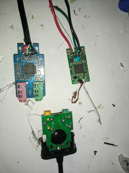
I bought 2 other usb sound brands, an axagon, which looks like a dud, the other one, ugreen us270 had a similar chip namely Cmedia HS-100B while the behringer mic 2 audio had a Cmedia CM109.
Needless to say the one with the Cmedia HS-100B works perfectly with the usb B connection. I could not hear an audible difference between the HS-100B and the CM109, yet the ugreen was 1/3rd of the price....
I am however having one last issue it seems. The mic works fine for 30s-1m then the sound becomes very low, re-plugging the usb makes the mic work fine again, what could be the issue in this case?
@axy_david Price isn't a good guide for mass-produced electronics. A lot of moderately expensive (£100- 300) desk microphones use capsules like the JLI2555 that Matt has specified. The only way to know is to crack them and have a look inside, but people who do are on YouTube so you can see what I'm getting at.
Once you creep into the £500 and upwards they do start using more expensive capsules but a lot of those can be bought for around £80-150 and all you need is either a donor body or make something like Matt's here. Beyond those, you're getting into highly specialised machining. There are a few tours of the Soyuz factory in Russia where you can see tradespeople machining brass down to two-micron tolerances producing what can only be described as complete works of art. Of course, the capsules are pretty much copies of the Neumans from the 1960s.
The slow loss of signal is usually caused by a DC biasing or supply issue but it's hard to take a proper guess without actually taking measurements. Anything that has a time-domain effect of seconds to even minutes is almost guaranteed to have a capacitor at its heart, although there are others.
I would be tempted to remove the USB C ADC and test the output directly into the microphone port on your sound card. See if you get the same issue and that might offer a clue.
I'd be checking the supply voltage across the THAT1512 (+30 from 4 to 7) and +15 or -15 between each one and the 0v (common).
Keep an eye on it as the output voltage falls and make sure something isn't driving the supplies down.
Fault finding is never easy but "divide a conquer" by separating the problem into halves is usually the fastest route. Hence, remove the digitizer first and see if the THAT (instrumentation amplifier) can still produce a reliable signal. If it does, the issue is likely the blocking capacitor and the DC bias is leaking into the ADC causing it to build up a fixed DC and effectively not leaving headroom for the small signals to operate.
The main thing is you are making progress and learning in the process which is all anyone can expect. I'm the wrong side of 60 and I learn something new every day. My current niggle is trying to figure out why the cancellation pressure isn't working on these Chinese K47 copy capsules. I'm starting to think they aren't vented by the way they behave!
Take everything I say with a pinch of salt, I might be wrong and it's a very *expensive* way to learn!
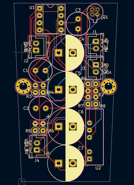
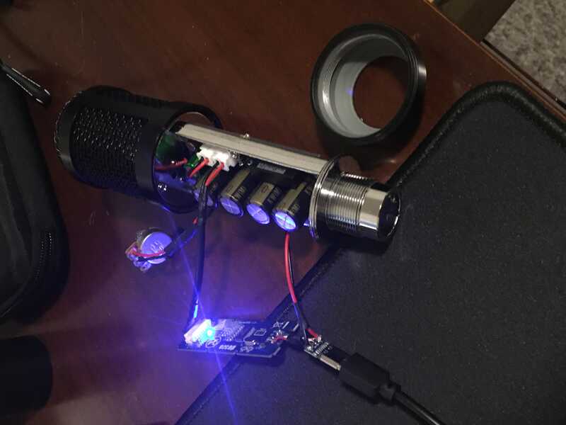
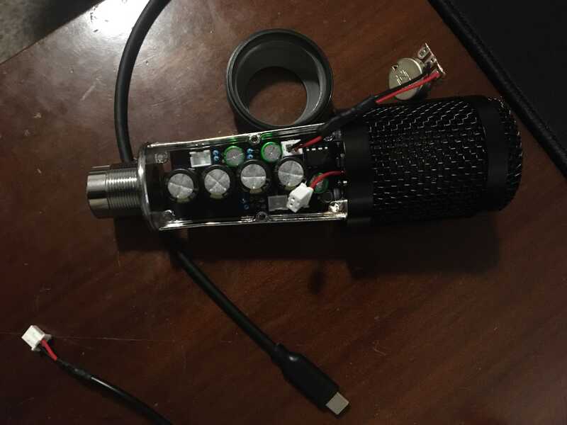
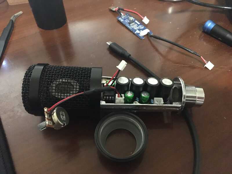
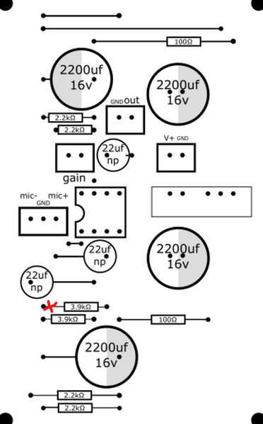
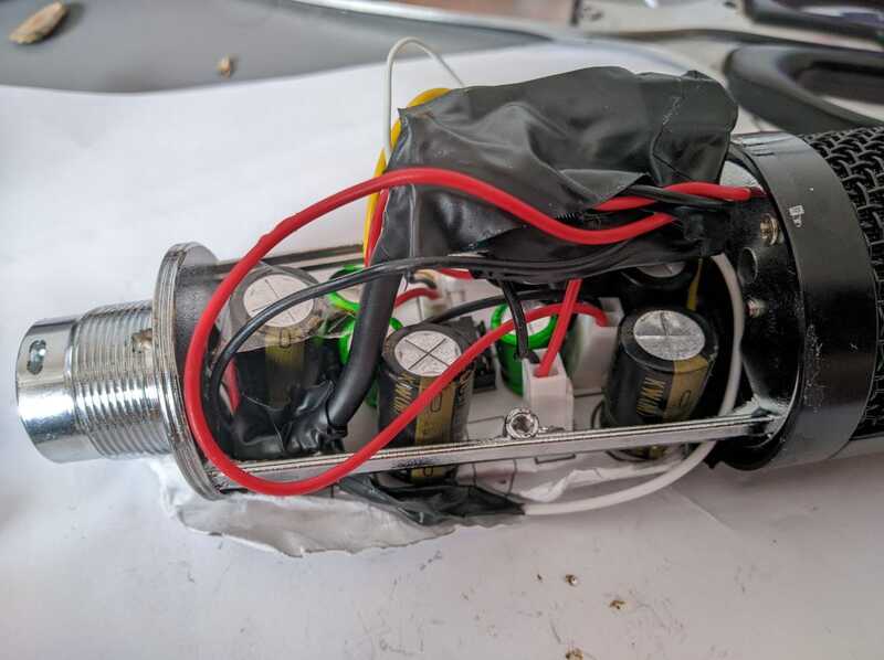
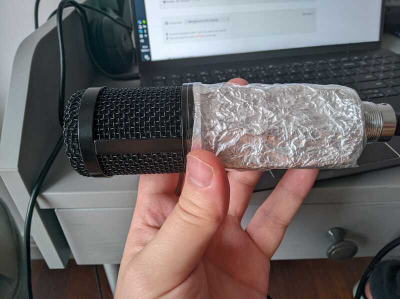
I completed my build. I used the body of a cheap xlr-microphone on amazon (BM-800, $25 and has a metal casing). The interior space was tight, so I created a custom pcb. I converted the xlr plug to usb-c by 3d printing a mount for the female usb-c connector. I also 3d printed a mount to hold the mic capsole. I used a 1k reverse log potentiometer for volume control. It works and sounds great! Here are some pictures..
@pygmalion MEMS that's it.
You can't hear the subsonic but that doesn't matter - one of these bad-boys would be simple and more accurate I would imagine.
You'd have to mount it to something physically connected to the motor of course. I could well imagine that any audible frequency it "hears" could be easily filtered out by the computer.
I also looks like you're going to need an FFT to get the best from this but that's over to you because my maths is at baby chicken level.
In this case, I think using an accelerometer like LIS3DH or ADXL345 is the better solution, and has been proven to work with the Raspberry Pi.
Speaking of MEMS devices, I tested my INMP441 I2S MEMS microphone. I burnt GPIO19 on my Raspberry Pi 4, so I had to activate one of my Raspberry Pi Zeros, which was really annoying. These I2S MEMS microphones are actually very good; the measurements with the INMP441 are about as good as the DIY Perks microphone at constant gain. It seems to me that for sound measurements with the Raspberry Pi, it does not make sense to go to so much trouble to build the setup around a condenser microphone when you can just buy the INMP441 I2S MEMS microphone for $2 and attach it directly to the board.
Here is also a very useful video comparing Electrolet with I2S microphones:
I also have not quite given up on the idea of controlling the gain electronically. With two SIP-1A03 reed switching relays and two GPIO pins, one can set four different resistances and supply them to Matt's amplifier.
That's it from me on this subject. I can report on the electronically controlled amplification with four resistors after I have tested it, if there is interest. Note that this will not be so soon as the material takes about a month to come from China.
Upon further inspection it seems that one of the resistors was not properly soldered, i made a few adjustments to the design so it would fit into a smaller board. Now it seems to work fine. Here is a sample, I do not hear any interference or noise, but I can hear some dogs barking really far away in the distance.
@lmarzen Oh maaan I totally have a similar mic body that actually was usb B by default however I did not manage to fit the prototype board inside of the mic! I would be forever grateful if you could share the template file so that I could print such a board so I could fit the circuit inside the mic! Pretty please?
@axy_david Nice man! Brilliant bit of debugging!
I feel your pain with the "room" issue but those BM800 mic bodies, cheap as they are, are a great time saver!
Looks like you chose decent-quality electrolytics though, that's a good start!
Matt's design is overcomplicated, particularly for this build. You simply don't need balanced lines like this - especially not in the body! Remember, keep it simple!
@Imarzen has done a version of what's commonly called the OPA Alice (because it uses an OPA1642 op amp as I recall) but that's a far superior circuit for this body design.
There's a US company that's done an even better version (if you're anti-op-amp) that uses a very clever FET layout with some dominant pole compensation on the impedance matching.
I'm currently designing (well, waiting on the parts) for a Cockcroft-Walton generator to give us 48v phantom power so you can use the really fancy capsules if you want OR as a circuit to power things like the BM800.
I'm going to have to order one of those USB C wotsits (ADCs) so I can try mine vs. Matt. It's great being able to work with such a master of physical design.
I have to say though, putting an ADC inside a mic that was designed for phantom power over a balanced line seems little odd. There are a few "donor bodies" (Samson makes a great example, C01U Pro) that outputs to USB which makes things a whole lot easier when it comes to wiring it all up.
Take everything I say with a pinch of salt, I might be wrong and it's a very *expensive* way to learn!
@pygmalion You can do it with a digital potentiometer more easily mate.
All you need to do is make a non-inverting amp (two resistors and your choice of op-amp) and put a very small resistor to ground (say 1K) and say 10K in the feedback circuit. Now put the digital pot in between the 1K and ground and you can adjust the gain of the entire circuit with a simple I2S input and a few lines of code.
You do have to be aware these devices can generate some HF noise so they need decent decoupling/bypassing (capacitors close to the device).
But they are essentially resistor chains controlled by MOSFET switches so they can just generate a binary sets of on/off and determine the signal path - therefore the resistance.
Looking forward to what you come up with here though!
Take everything I say with a pinch of salt, I might be wrong and it's a very *expensive* way to learn!
@lmarzen Oh maaan I totally have a similar mic body that actually was usb B by default however I did not manage to fit the prototype board inside of the mic! I would be forever grateful if you could share the template file so that I could print such a board so I could fit the circuit inside the mic! Pretty please?
I optimised the circuit board so that it is only 4 cm x 5 cm. See https://forum.diyperks.com/postid/3174/
@pygmalion You can do it with a digital potentiometer more easily mate.
All you need to do is make a non-inverting amp (two resistors and your choice of op-amp) and put a very small resistor to ground (say 1K) and say 10K in the feedback circuit. Now put the digital pot in between the 1K and ground and you can adjust the gain of the entire circuit with a simple I2S input and a few lines of code.
You do have to be aware these devices can generate some HF noise so they need decent decoupling/bypassing (capacitors close to the device).
But they are essentially resistor chains controlled by MOSFET switches so they can just generate a binary sets of on/off and determine the signal path - therefore the resistance.
I do not understand what you are suggesting - could you give me a schematic? I already have a digital potentiometer MCP41010, but I do not know how to use it as it is only rated for 0V to 5V and the voltages in Matt's amplifier are -15V to 15V. It would be easy if I had to supply voltage to the MAX1512, but I have to connect a resistor RG. Very impractical. I googled the problem but could not find a solution.

