Okay so I am back with renewed energy. I can't start any new projects till I finish this project.
I get sound, sometimes fairly clearly, sometimes not. My lips have to be super close to the microphone. I am unsure what is wrong.
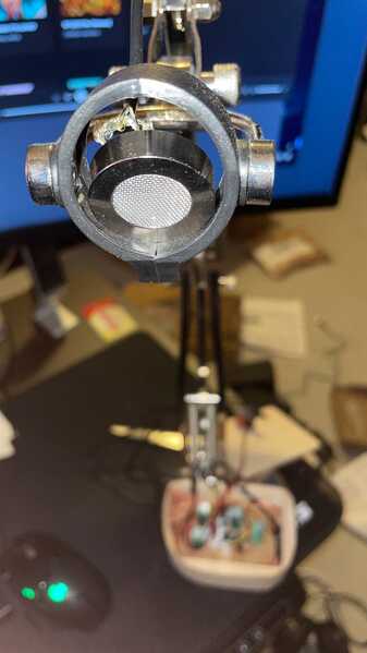
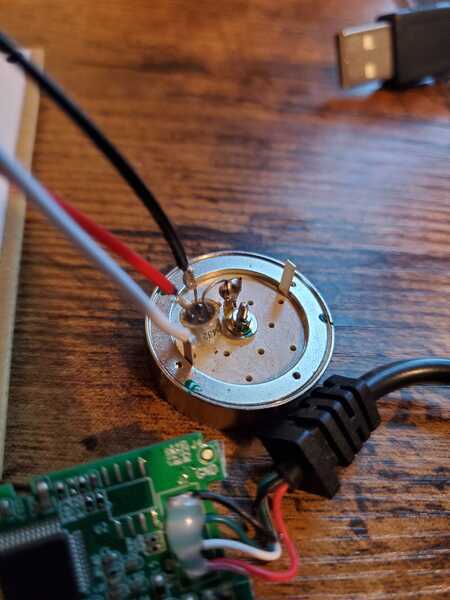
Currently I have the capsule without any cover, just because of testing and wanting to do things correctly.
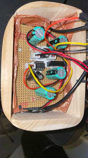
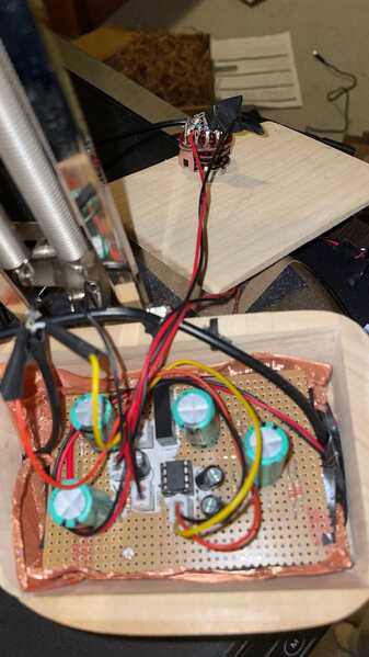
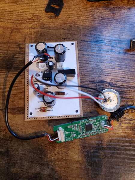
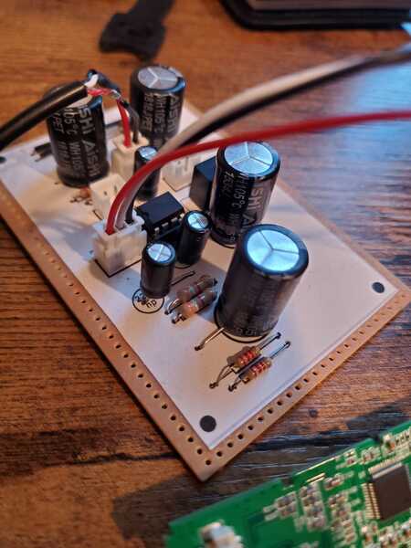
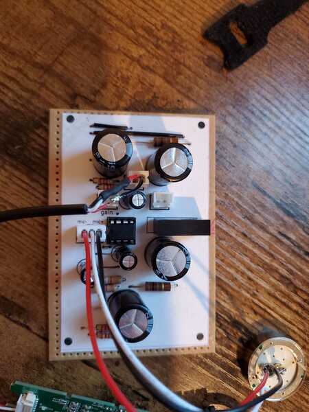
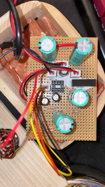
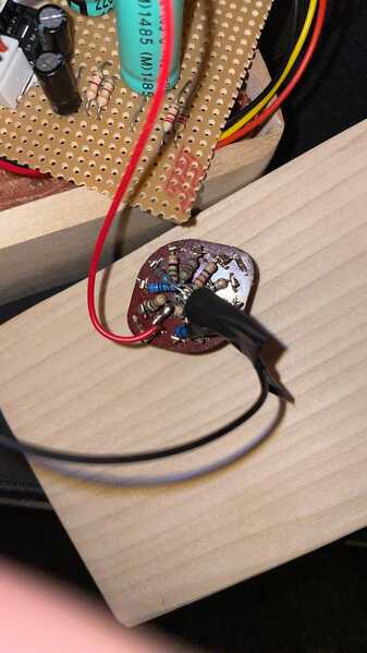
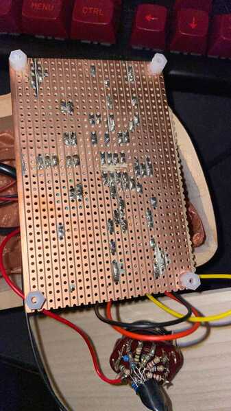
Here are the images of the current setup:
Now I also redid the audio recordings
Please let me know your advice and input, I would really like to complete this project.
My friend suggested if it is perhaps grounding somewhere where it should not be
@someguy There are a few things that can cause this and finding what it is depends a lot on what sort of test gear you have to hand. A DVM (meter) is essential and they're not that expensive now. A scope ... that's a bit more esoteric.
Grounding issues usually result in a fair bit of noise and (naturally) you'll hear that because it's often going to be that 50/60Hz tell-tale from the mains.
My big issue with the design as is is that there isn't a DC path for the JFET's gate bias. I've seen Doug Ford (former chief designer at Rode) discuss this at EEVBlog and he was baffled too; although in that case he was referring to the internal JFET in an everyday electret condenser. You know, the ones they give away as booby prizes and fit to cheap electronics).
JFETs are supposed to have a DC path to ground to bias the gate electrically but for reasons I can't fathom, this design works in practise for many people! In order to work, a JFET's gate should be slightly negative with respect to its source terminal, reverse biasing the diode junction formed from drain to gate. Didn't work for me which is why I set about re-designing it from the ground up but that's a different discussion.
Matt knows I usually prefer a BiFET op amp approach (I use the TL072, but the OPA1642 is a better option). You can see those things mentioned earlier.
Matt's design relies on a rather beautiful effect that means the capsule and the high impedance amplifier are fully screened before the signal leaves the "head". The extra screening, balanced line and so on are actually not that important because the signal path is already "low" impedance (passing a "large" amount of current - relative to what the capsule does). That was a light-bulb moment for me because I've been testing these capsules via a short length of screened cable and most of what I get (pre-screening) is a LOT of mains hum.
The "gate bias" problem can be addressed pretty easily although it's unlikely to help given that other people seem to be getting decent results. Don't worry about why this is important but you can try popping a 1Meg (or larger) resistor from gate to ground and re-testing. This is a pretty quick fix and it'll work or it won't. It won't break anything.
Grounding issues are a devil to find - they tend to show up as lots of noise but you don't have that issue so it's not a ground loop.
You may have a "dry" joint on the board, you might have accidentally shorted something to ground for example; or conversely, not grounded a load resistor.
So debugging this sort of thing isn't the easiest thing in the world... small AC circuits are a bind like that because the "magic smoke" rarely sets in. For example, I toasted a TL072 yesterday because I was careless with a ground connection and shorted something. Took me ages to work out what was wrong because I blamed everything BUT the chip which had swung hard to the positive supply.
Another thing that can do this is a DC bias where it doesn't belong. The THAT1521 at full tilt per Matt's design is giving a 60 dB gain - that's a factor of X1000!
Now imagine you had a just a fraction of a volt DC sitting on the input terminal - that's getting amplified by 1000 and it will send the output hard against one of its supplies (or as close as the design allows, many op amps can't make either or both supply rails due to internal limits). Although that DC gets blocked on its way to the next state (the USB digitiser) you don't notice it BUT it means the amp has nowhere to go where your (very small) signal is concerned so they only way you can get anything out of it is to scream into the mic, producing a level which just overcomes that small DC input error.
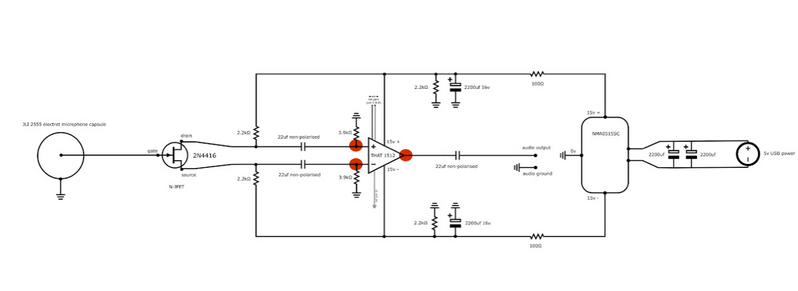
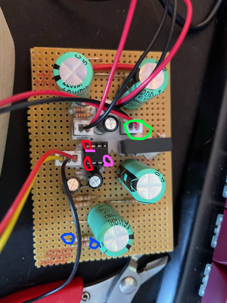
This is what I suspect is going on here, so you should check the three points I've marked in red here with a voltmeter to ground (common) and see if there is any DC voltage.
Also check for a voltage between the two inputs - again this should be 0V too. A small voltage will develop across the gain resistors - how much I can't say for sure but it will be the largest at the lowest volume click.
There are other tests you can do, but these will give us some idea as to how everything is working.
While you're at it (if it's not obvious) you should check the supplies to the THAT1512 to ensure you're getting +15V and -15V at the respective pins (and 30V across the whole device). This helps check the main grounds are solid and the power is operating as it should.
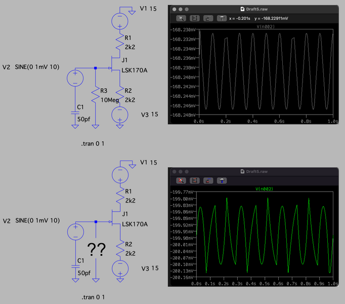
As a matter of interest (and I'm by no means an expert with SPICE simulation) but this shows what appears to happen when there is no DC ground path. Looking at how the sim does things, I can only guess that the capsule generates a negative bias as it moves. LT SPICE is a free download from Analog Devices (it was developed from SPICE and was formerly owned by Linear Technology).
This isn't an exact representation of the capsule but it's the best model within my own skills. Although the sim seems to suggest dramatic distortion, the actual output seems pretty good and it's hard to argue with that. I expect this is a limitation of SPICE as a real electret doesn't work exactly like this.
The output is pretty feeble because the design is only there as a phase splitter.
Take everything I say with a pinch of salt, I might be wrong and it's a very *expensive* way to learn!
@marcdraco I think I broke something, so I tested the following:
So The pink was tested together, and it had 0 volts, the blue also had 0 volts, and the red as well.
This led me to test what power was coming in, it was 5 volts or 10volts depending on if I use the V~ or the V- on the multi-meter
This morning I broke two wires, and had to reconnect them (the power wires). So Now I just get static out of the microphone.
I cannot for the life of me, figure out what I'm doing wrong here. Coming onto the forum and asking this was my last resort. I have everything soldered together and for the most part wired up how I think it's supposed to go but when I plug it into my computer to test and make sure it's working it recognizes the device but doesn't get any sound input. If anyone is willing, could someone check my work and advise me on what to do? that would be extremely appreciated. My current hunch is that perhaps I bought an incorrect component.
V~ - that sounds like the A/C. There shouldn't be an A/C there but not to worry, it's probably just noise. Modern DVMs pick up all sorts of rubbish.
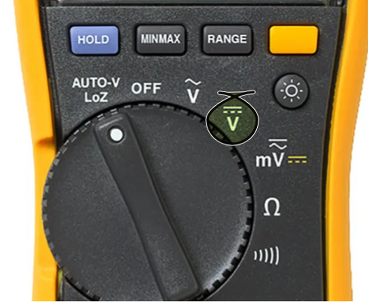
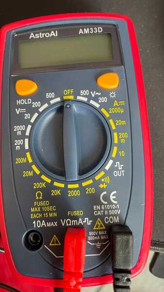
Always test on the DC setting - it's often a little like an equals sign only the bottom bar is "dotted". I've ringed the range on this Fluke. Some meters will "guess" A/C or DC on a single range but that can be more confusing.
Finding issues on Vero/stripboard can be an utter nightmare but let's see what we can do.
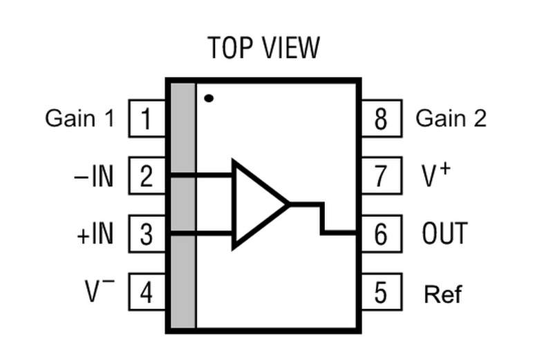
First of all, VERY carefully remove the THAT1512 op amp from its socket. It's difficult or impossible to get accurate readings from anything when there's silicone involved. The THAT1512 is a specialised version of an industry-standard. I've drawn it here:
When you power the board, the DC measured at pins 4 and 7 should be +30 V (your black lead goes to pin 4 and the red to 7. If this is off by more than a volt or so, you've got power issues.
Next, find your "common" (0V) connection. The easiest one is probably the BLACK lead coming from the USB 5V rail. (Check on that DC range that this is the case beforehand). Ref (pin 5) is normally connected to 0V so that's another place to pick it up.
With the Black lead connected to Ref or 0V, you should measure (using the RED lead) +15V on pin 7 and -15V on pin 4.
All other pins, referenced to pin 5 should read 0V DC.
If all that checks out, remove the power.
The resistor chain (volume) is mounted between pins 1 and 8. With the chip still out of its socket and with the power removed you should be able to measure the various resistance as you move the switch. Very low values like 5 ohms are tricky but it will give you an idea.
Pop the THAT1512 back into its socket, power on and repeat the VOLTAGE tests only, that's the black lead to pin 5 and the voltage on pins 4 (-15V) and and 7 (+15V).
Get back to me once you've completed those tests and we'll go from there. I know this is a very slow process but we need to establish that the power is wired correctly, is functional and that the "magic smoke"* didn't go unnoticed.
* Magic smoke is a joke we use in the design game for when you plug something in and due to a wiring or (heaven forbid) design error causes a component to overheat and go up in smoke! The thing is that it's quite possible to jigger semiconductors without so much as a click. They just stop. I had a TL072 blow on me a few days ago and because they are usually so reliable I blamed everything BUT the chip!
Take everything I say with a pinch of salt, I might be wrong and it's a very *expensive* way to learn!
@mrroomba I'm pretty sure it won't work without the GAIN switch wired up so you need to do that first. Visually, it looks fine but if you can follow the instructions I've given in just above this post and make sure the voltages are showing as they should, that will save us a lot of guesswork.
Looks pretty decent work for a non-professional.
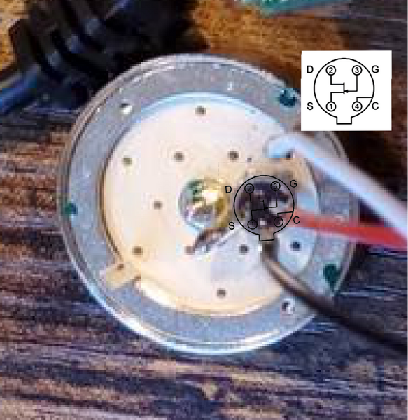
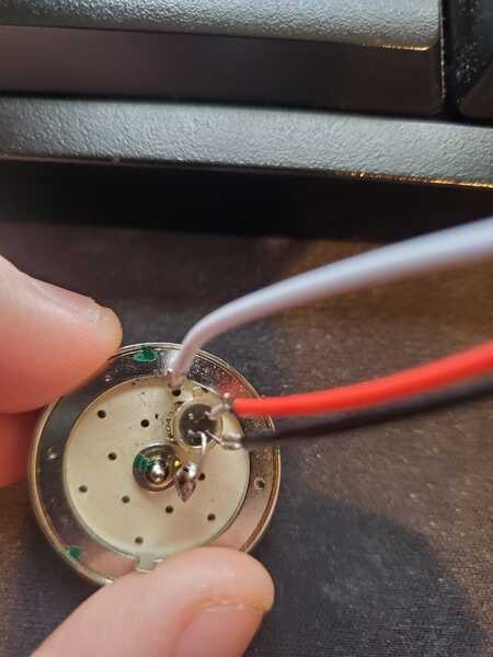
This might be the issue though. It's really tough to see given the way the network mangles these pictures but if I've correctly identified where the tab is on the 2N4416 JFET (and trust me, I really hope I'm wrong) then this is your issue.
Do let me know - that's a pretty pricey transistor if this is the case. Can you triple check this because it looks like you've trimmed off the gate lead by mistake.
Take everything I say with a pinch of salt, I might be wrong and it's a very *expensive* way to learn!
@marcdraco I trimmed it based on what I saw in the video, here's a better photo of that spot up close.
@marcdraco I am totally cool with slow, i just really appreciate the help.
So tested it without THAT1512, and i got nothing no voltage anywhere.
The voltage coming from the USB C is testing at 5 volts, and then I flipped over the board to test voltage on everything and some of the capacitors are showing 0 volts.
The 15v +- isolator: is showing 5 volts, so I think something went wrong.
Please let me know what I should test, or swap out in terms of parts. Just an FYI I did have electrical tape on the back
I very much appreciate the help.
Here are close up photos:
The voltage coming from the USB C is testing at 5 volts, and then I flipped over the board to test voltage on everything and some of the capacitors are showing 0 volts.
The 15v +- isolator: is showing 5 volts, so I think something went wrong.
@Someguy You have 2 capacitors facing the wrong direction, specifically the two for the isolator. This might have done some damage to your components, so check if they're still alive. Also double check if the traces between the THAT1512 are properly cut with a multimeter, making sure to disconnect the components connecting them. Visual inspection is fine but as accurate as measuring for continuity.
To test if the NMA0515 is still alive, simply connect two large value resistors between the outputs (minimum 500 ohms, but larger is still better so use some super common 10k resistors if you have them laying about) and provide 5V power to the IC. Remeber to disconnect it from the rest of circuit so you only measure the IC and nothing else, you can do this by desoldering the resistors and wire connected to the +Vout, 0V and -Vout pins. You can then measure the output to see if your multimeter measures 15V between +Vout and 0V, -15V between -Vout and 0V, and 30V between +Vout and -Vout. I would recommend using an oscilloscope here if you can so you can see if there is a lot of ripple, it should be 15 mV peak to peak so if its larger than that the IC is damaged but still functional, or a fake.
Remember to source any silicon from a reliable vendor like Mouser or DigiKey rather than Ebay or AliExpress. Ebay/Aliexpress has a fun tendency to relabel other ICs as the one you want to buy.
If there is still a problem after this, please post another question here so we can help you figure out the issue. 👍
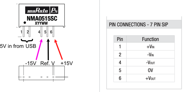
The NME5015SC isolator as you referred to it is a monolithic voltage multiplier and inverter. It takes +5V and through the magic of small inductors and amazing MOSFETs it generates 30V.
Love that word "monolithic" it means "one stone" but in this context it really means an entire and fairly complex flying capacitor and inductor circuit all set in a slab of epoxy. Very neat and highly convenient when you have ICs like the THAT that are difficult to power.
The nuisance with these little beggars is they don't come in a package that you can easily mount in a socket (as here).
If you can carefully desolder it you can test it in isolation to make sure it hasn't gone to Silicon Heaven (which is where all the toasters go)* you can check it in isolation.
Find the +5V from your USB supply and attach it to pins 1 and 2 with pin 1 being 5v and pin 2 for ground. You don't need to worry about capacitors when you're testing insolation like this. You should now be able to measure the + an - 15V putput with respect to (the 0v or black lead from your DVM) to pin 5 . I've marked this out on a diagram with the purplish colour indicating your negative rail.
IMPORTANT: the according to the manufacturer, unloaded voltages can be quite high (perhaps as high as 30V) because the output isn't regulated, but that's normal and just means it's working unloaded.
If you have a scope, you'd see this is going to ripple a bit but your DVM won't show that. What matters is you have the correct voltages at the output of the chip. I believe that it's short-circuit protected so if you've accidentally shorted something. However (sorry Matt) I did notice another whoopsie on the circuit as presented as the maximum capacitive load these devices are rated for is 47uF (with 10uF typical). Matt's over engineered it a bit with 2200 uF buffered by the 100 R resistors. We're expected to use SMD inductors and capacitors for filtering. Course this stuff is dug into the data sheet like a tick and finding it is more luck that good judgement and we know it works because we've seen and heard them.
I'm working a little bit in the dark because I haven't built this design - I've been working on a Mk.II that's simpler and more suitable for people on (cough) limited (cough) budgets. 😉
Anyway, could you give this a go and see what your DVM spits out. When you've done that you might want to try soldering the device in on flying leads so you can see what happens it's connected.
If you're going to do these tests though, remove the THAT1512 just in case anything goes sideways - we don't want to cook that!
Marc
-------------
*That's a Red Dwarf joke that might be lost on you, but many Brits will get it.
Take everything I say with a pinch of salt, I might be wrong and it's a very *expensive* way to learn!
@marcdraco Awesome! I got a 25- and 25+ reading on the pins, when in isolation!!!
So it seems like it is working!!!
Ahh so that is why monolithic is for CPUs and GPUs are called that, I didn't know its meaning was "one stone".
I am reinstalling the isolator back into the board, and trying to clean up the solder as it has spread across the channels.
Still getting only static again, which really sucks as it was capturing some sound before
Sounds good, so it's definitely working 25v would be reasonable for a no-load condition.
If you've got "loose" solder on the go (very common with strip board, even the best of us have trouble with the stuff) it does tend to bridge between tracks - often so thinly that you can't see it without close inspection.
I don't have the circuit but I believe it's probably got a "foldback" short circuit protection which would mean it effectively shuts down if the load exceeds some preset amount.
It's quite a simple thing to do, you just insert a very small value resistor (say 1/10th ohm) in the output and measure the voltage across it vs. a reference. If the current exceeds a preset limit, the voltage across the resistor rises and the output can be shut down.
Good luck and let me know how you get on!
Take everything I say with a pinch of salt, I might be wrong and it's a very *expensive* way to learn!
@marcdraco Here is the link to the schematic:
https://diyperks.com/ikyteech/DIY-Perks-Mic-Preamp-Resource-Pack-V1.1.zip
what I have been doing is using a razor blade between the tracks to ensure they are clear.
What do you mean by inserting a resistor on the output? is this with it not in the circuit? My apologies, I don't know much about electronics but have been learning
@marcdraco I trimmed it based on what I saw in the video, here's a better photo of that spot up close.
Well that's a relief! Expensive parts these.
If you don't mind me asking, why did you colour code Drain as black and Source as red? It's just that drain is (usually) more positive than the source in most applications, so drain would be red and source would be black. It's immaterial if you know of course but I want to make sure you have it the right way in!
Take everything I say with a pinch of salt, I might be wrong and it's a very *expensive* way to learn!
@marcdraco Here is the link to the schematic:
https://diyperks.com/ikyteech/DIY-Perks-Mic-Preamp-Resource-Pack-V1.1.zipwhat I have been doing is using a razor blade between the tracks to ensure they are clear.
What do you mean by inserting a resistor on the output? is this with it not in the circuit? My apologies, I don't know much about electronics but have been learning
The resistor is a very small SMD part (there will be two most likely) but all that stuff is part of the monolithic design and we don't need to worry about it. Current fold back circuits just protect the outputs from parts like these in case you accidentally short circuit something.
If there's a short on your board for example, the device will shut itself down and not produce much in the way of voltage or current so it doesn't go up in a poof of magic smoke. 😉
There's loads of info on the web but you don't need to know this stuff in order to use the parts. Some clever designers already did that work for us!
https://en.wikipedia.org/wiki/Current_limiting
Take everything I say with a pinch of salt, I might be wrong and it's a very *expensive* way to learn!
@marcdraco Oh man that is sick, thank you - that actually makes me very relieved as I am sure I would have shorted this out many times.
So placing the isolator back in the circuit shows that is is getting the input of 5V but is producing 0 output.
I am thinking of pulling out all the components and then rebuilding the circuits - thoughts?
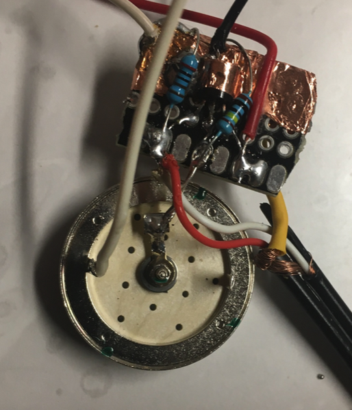
That horrid thing that looks like something crawled out of a crashed UFO the prototype (which needs a PCB to be fair) of the new head unit I've designed for Matt's desktop microphone. This early version (which is not recommended for anyone!) only uses two resistors and 9V battery (it will work with 5V) and drives a microphone input directly! Noise is extremely low and quality is surprisingly good. Well considering it would look more at home on a pile of scrap electronics ...
Next job is to make "a round tuit" (so I can "get around to it") that will solder directly to the back of a JLI microphone (it works on any of the fetless condensers) so there's less to go wrong.
Linearity is "m'eh" but perfectly acceptable - not going to worry Neuman just yet though with a THD in simulation of around 0.1% at Khz which isn't going to blow your hair back.
This is more a proof-of-concept for large diaphragm condensers - the rest of the supporting circuitry has to be fully tested but this version will be more portable and far less power hungry so it will make a great outdoor or live microphone. Naturally we need @diyperks to come and design a shell (hint, hint) for this.
And if you've been following what I'm up to, yes that IS copper slug tape acting as part of a ground plane.
Take everything I say with a pinch of salt, I might be wrong and it's a very *expensive* way to learn!
@marcdraco Oh man that is sick, thank you - that actually makes me very relieved as I am sure I would have shorted this out many times.
So placing the isolator back in the circuit shows that is is getting the input of 5V but is producing 0 output.
I am thinking of pulling out all the components and then rebuilding the circuits - thoughts?
Sounds like you have a short to ground on one of the supplies. If I had a penny for every time I've goofed like that on strip board... I wouldn't have to make my own mics!
Fastest way to find that is to pull the THAT1512 from its socket and do resistance tests from the power inputs to the relative positions on the inverter. As I've mentioned strip board is a nightmare in this regard. Be aware that capacitors (esp. large ones) appear to be a short for a fraction of a second while they charge up so you might hear your continuity tester bleep. It's the continuous tone you need to worry about if it's somewhere that's not supposed to be shorted! 🙂
It's important to remove the chip when you do this because it can get in the way of your tests. Ideally, I'd take the inverter out too but that's not too easy to keep doing and there's a chance you could snap a lead and.... yeah, that's not good.
Normally I'd say you could use an old scope (the digital ones don't work for this) and make something called a Scope Octopus. I've got part way through making a true digital one but the ADCs I have are a bit too slow to make the trace quickly enough. They're something worth having if you can pick up an ancient cathode ray scope in working condition. You only need a transformer, some probe leads and a couple of resistors but they draw patterns that can identify all sorts of components and even faulty silicon chips in some cases. Digital scopes are too rapid and accurate so they just produce mush. Ironic really.
Here's a lovely clear example of how to make your own. An old scope might set you back 50-100 quid (less if you're lucky) and you can just use it as an octopus for fault finding.
https://www.jammarcade.net/simple-component-tester-a-k-a-octopus-curve-tracer/
Take everything I say with a pinch of salt, I might be wrong and it's a very *expensive* way to learn!
@marcdraco woah this seems sick! I have no clue how this works, but ti seems super compact and useful
@marcdraco I will give this a go, and if it doesn't work I'll just pull out all the components and redo the entire build with a new board
Dumb question, which setting do I want to do these tests:
@marcdraco Well, tbh I had everything wired up the way it was in the video before, but when it didn't work I figured it was my bad soldering job and re-soldered the microphone to a 3-pin connector as a way of guaranteeing it wasn't the connection that was the issue. Since the connector wires were already secured in their little plastic housing I just soldered the microphone connections by the markings on the project board.
@marcdraco I ended up rebuilding the entire circuit, I think I have ruined one of the components and have no idea which one, as It still isn't producing any sound. One thing I noticed is when I placed the resistors in they were heating up so much with the soldering iron - could that have ruined it
edit: Tested the resistors they are fine, the only problem is that it is now picking up any sound, the static noise is very very quiet
@marcdraco I will give this a go, and if it doesn't work I'll just pull out all the components and redo the entire build with a new board
Dumb question, which setting do I want to do these tests:
No such thing as a dumb question. If you don't know, asking the question is the fastest way to get answers. I'll assume you found the right setting but if you need more help on test gear just shout up.
While it IS possible to kill a resistor by overheating it, it's actually quite difficult. They usually fail when the designer puts too much current through one -or- a component fails causing that to happen and then... you guessed it, magic smoke!
Semiconductors are more fussy - most can only take about 10 seconds at full heat before they bit the dust, some less than that. It's all mentioned in the spec sheets. You've got your THAT1512 in a socket so that's probably safe.
Capacitors like these tend to fail when you put them in the wrong way around but magic smoke usually tells you that. Or a huge BANG followed by a volcanic release of electrolyte... (all over my mother's best carpet, she wasn't happy about that - so I'm a bit more careful now I'm 43 years older).
Testing the THAT1512 is going to be more troublesome. Did you say you had the correct voltages at the supply for that now? Remember that with your BLACK (common) lead fixed to 0V, you should get +15V at pin 7 and -15V at pin 4. Also 30V DC between those two.
I don't have this setup as I've said, but there is one other thing you can do (for now) - poke it with a finger!
No really...
If you disconnect your mic input (and power the circuit) putting your pinkie on either of the input leads SHOULD cause the output to buzz like a M/F provided your volume is set to 60dB (about 5 ohms on the gain pins).
If not, don't worry, you can do the same test at the output - but you'll need to disconnect the USB ADC and do the same thing. I haven't tried this but it's likely that the ADC is sufficiently sensitive to pick up mains hum which is annoying as hell when you don't want it, but a useful "quick and dirty" signal source for testing high-gain, high impedance circuits.
Your body picks up the magnetic field and acts like an aerial. DON'T touch the mains though! There's enough of a field in most homes to do this.
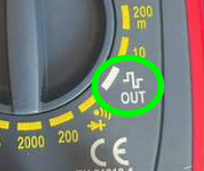
A signal injector would be useful and it looks like you have a crude one on your meter.
This looks like a square wave generator. Not a clue what it's peak amplitude is though which is a shame. I'm not sure it's safe to use unless it's limited to (say) 5V and the manual isn't 100% clear... referring to silicon diodes as tubes (eeeeerrr...)
All that said, it's probably quite safe to use.
You should be able to inject a signal from the positive probe (with the black lead held on a common, 0V) to various points in the circuit but remove the mic capsule for safety, just in case!
I'd test the digitiser first. You can desolder that and inject the signal to its input wires. If this doesn't show anything, you have to suspect the digitiser is faulty or something is awry there. I note th
If that works OK, reconnect the digitiser, turn the gain knob down, and inject a signal at the MIC input (either input lead as we're not looking for phase and noise effects). At some level of gain, the output should start showing a signal (my guess is it won't) and this is where we can start looking.
It's important to make sure you disconnect the bits you're trying to test. The ADC should be self-contained so it'll power when you plug it in - you need to put the signal in at one of the inputs. (A lot of this is easier for me because I've bought in signal injectors over the years, but you can get them for mobile phones. In fact, a mobile phone headphone output is another (poor man's) signal source with a low impedance so it will drive any of these circuits.
If you want to go down that route simply grab a £1 headset from your local pound store and chop the earpiece off. The wires a quite delicate so be careful separating them out. I sometimes use a hot knife to cut the insulation - a soldering iron works at a pinch - but the plastic might give off toxic fumes so a proper tool is always preferable.
Let me know how you get on.
----- More about electrets
The proof-of-concept board above does essentially what a "Linkwitz mod" does to WM61A capsules. Some people will already know that so I've used it as a shorthand.
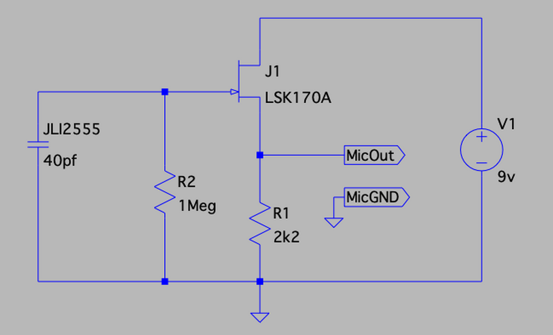
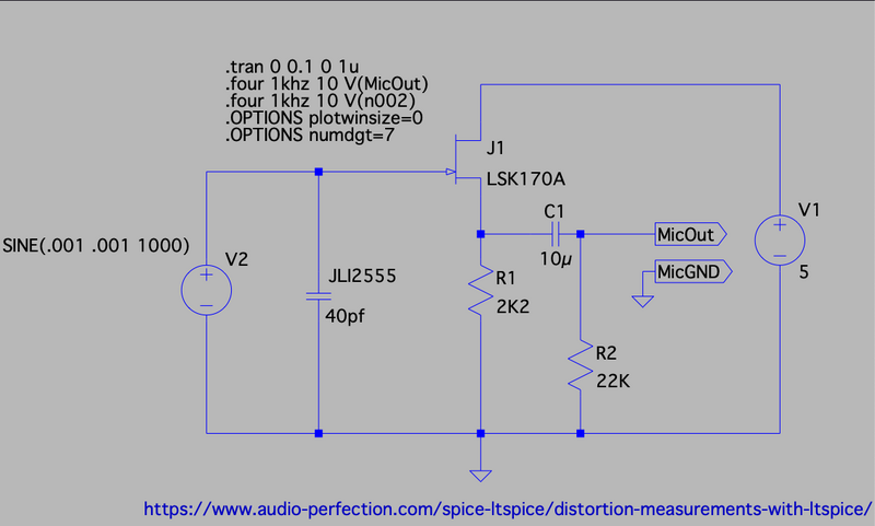
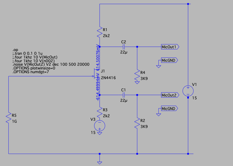
What it actually does is wire the JFET as a simple source follower like this (using the free LTSpice simulator):
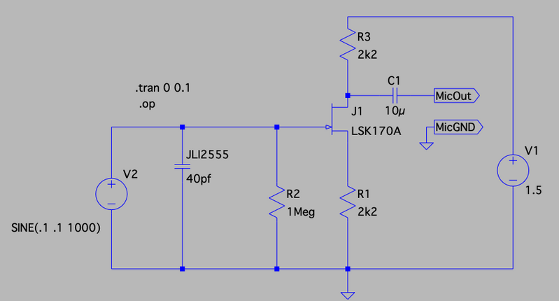
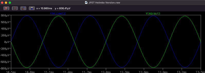
This will deliver 1mV p-to-p sufficient to drive a microphone input on a sound card or even a USB sound interface, but it really should be screened. A more "traditional" way to do this uses a common source or even something like this. With the output taken from the drain like this (I've added a source resistor to this version - much like the one used in Matt's - which forms a phase splitter but we only need a single phase.) I also added a small sine wave to the signal so you can try it for yourself. The wording (.tran 0 0.1) is a Spice directive and tells the program how and for how long to run the simulation - 1/10th second is all we need for this.
The source resistor (2k2 here) is still important and while these circuits work in simulators, practically they are limited by weirdness in JFET construction. JFETs are weird anyway if you're used to more common devices like MOSFETS (nice and simple switches) and BJTs, relatively simple and reliable. With NPN BJTs and N-type MOSFETs you drive the control terminal positive to get current flow. JFETs are "depletion" devices which means you have to wire the gate *negative* with respect to the source terminal and that's just weird. These circuits do that automatically - it's called "self-biasing" because the transistor biases itself when the power is applied.
While it works, it's far from ideal, particularly in circuits shown here.
The JFET is usually internal so it's all screened from noise sources: there's a superb animation of one being cut apart here. You can see the JFET on the backplate with its gate mounted to the backplate. You can see here how the backplate is separated from the charged diaphragm by a small spacer. These things are incredibly simple and yet amazingly powerful.
Matt's design does the same thing but in a much larger housing that looks gorgeous (I'm so jealous of his skills... well maybe not jealous, but I definitely admire them greatly).
Take everything I say with a pinch of salt, I might be wrong and it's a very *expensive* way to learn!
Finally!
The post you haven't been waiting for this is mainly for information and a correction for a previous error that caught me out in LTSpice so I'm thankful to Audio Perfection for help nailing down the correct settings to get a more accurate distortion measurement.
https://www.audio-perfection.com/spice-ltspice/distortion-measurements-with-ltspice/
Each circuit has a 1mV sine wave at 1 KHz to simulate a signal for measurement. Output is typically 0.8 mV to 1 mV - which is then amplified by a pre-amp such as the THAT1512 in Matt's design.
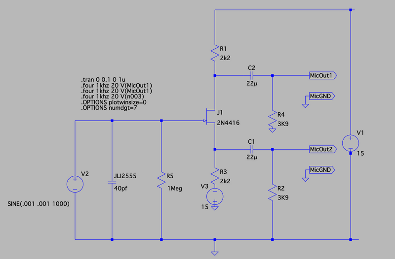
So from top to bottom, let's see how the various circuits perform starting with Helmke's original Alice front end:
This appears to be a very complex design because it separates the P48 phantom power input over the XLR. I've simulated the input to the preamplifier and put the internal current limited P48 supply in a dotted box.
It should be of no surprise that the circuit produces two identical (but phase reversed signals) which are then sent down the XLR. The 1mV input is dropped a little (0.8mV) but that's of no consequence. Predicted THD is 0.001169% and 0.000126% (respectively) but that's with ideal components and is, in any case far too low to hear.
Now the DIY Perks design (without the THAT1512 instrumentation amplifier).
Distortion here is raised to a staggering 0.79765% (predicted) and although that's audible on a pure wave, for speech... not so much so.
But can we get closer to Scott's design - but keep it nice and simple? Turns out that (according to experts) a way NOT to do it, self-biasing the FET works quite well. You'll note this design uses 5V only - so it does run from USB but I haven't included any supply filtering which is naughty! Predicted THD 0.003413%. I've also missed off the 1M+ resistor which is usually necessary for all these designs and can't hurt.
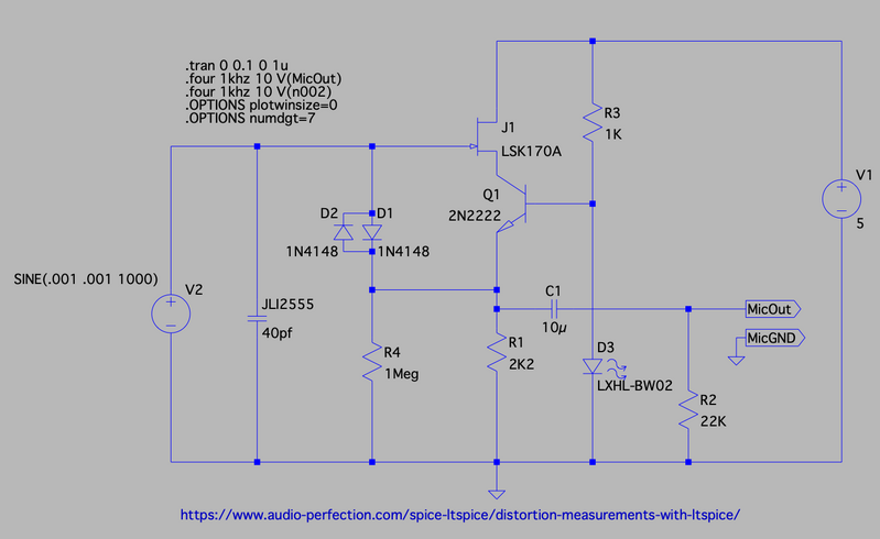
If you really want to go to the trouble of a constant current source, this is one way to do it - with a predicted distortion outside of human hearing at: 0.000226%.
The JFET current is set by a combination of Q1 and R2 and is a function of the emitter voltage which is set by an LED and a small resistor. RED LEDs are good for this and they're cheap. The resistor value isn't critical and should probably be a little larger than what I've used here. You can buy current regulator diodes which are actually JFETs that have their source and gates tied off and are sorted by current but the blasted things are expensive and it's often just as easy (and a lot cheaper!) to make your own as here.
An interesting thing with this design is the use of bootstrapping (from the emitter of Q1 to the top of R4) to linearise the diodes by making their voltage drop effectively almost 0.
This is probably the one I'll make the PCBs for when the rest of my FETs show up because it does offer a more reliable design and it's good down to under 5V. A bit of tinkering and it would go lower still but that's getting beyond what we need.
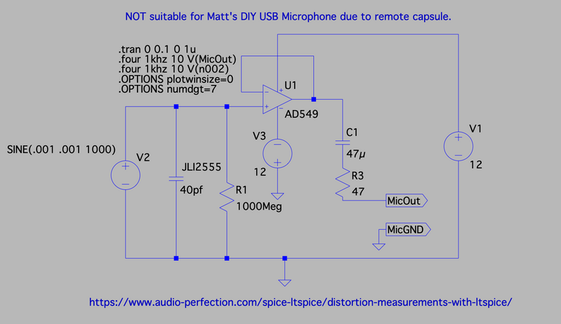
But the ultimate for full body microphones (think Neuman, AKG and so on) where the whole job lot is screened with a metal can and a faraday shield you can get the distortion so low that Spice wasn't able to measure it! This is a variation on the OPA Alice - a popular hack for screened mics including the horrid Neewer 800! The actual OPA Alice uses P48 per Scott's design above but I've kept it simpler here because ... I'm too lazy to do the 6V biasing circuit but it doesn't affect anything.
Predicted distortion is 0.0% which is, of course, impossible. As a summary of the various options you can see that a high-quality audio Op Amp with a JFET input like the OPA1642 (I've used a close alternative here) is by far the best option but that means putting everything in a screened can and that's not possible with Matt's beautiful design. Scott Helmke's Alice design is the best performing transistorised P48 design but like the OPA solution, it won't work over even fairly short cables because the noise pickup is horrendous.
It's quite possible to make a fairly small OPA Alice (using SMD components) but then you have the problem of getting the power to the circuit.
But comparing complexity vs. cost simple, self-biased JFET produces quite respectable performance and with the values shown has a low-frequency cutoff of just 0.7 Hz (which, to be honest, is a bit silly...) These circuits will all require some sort of further buffering and amplification as show however. I'm going to use a simple low-voltage op amp configured as a follower and then a x100 amplifier to get the signal to a respectable level.
| DIY Perks | 0.79765% | |
| Simple Bias | 0.003413% | |
| Helmke Alice |
0.001169% |
|
| Constant Current | 0.000226% | |
| OPA 1642 | 0.000000% |
Take everything I say with a pinch of salt, I might be wrong and it's a very *expensive* way to learn!
@mrroomba Sorry I miss some posts in the miasma of my long explanations about improved designs. Did you get it working now?
Take everything I say with a pinch of salt, I might be wrong and it's a very *expensive* way to learn!
@marcdraco Sadly no. I'm still a bit baffled as to why this thing isn't doing anything.
You could try some of the suggestions I've made for the other chaps here - no point me repeating the same old stuff, but you should start by checking your voltages are correct on the THAT1512.
Assuming that is correct, you should find a way to inject a signal into the circuit at various points (ideally with the THAT removed at first) so you can see if it's actually getting to the digitizer.
Simulation suggests that the source and drain terminals on the FET (at the microphone) should sit around 0.7 volts (drain) and -0.7 volts (source) when the mic is connected by there's no sound.
You should have +30 V measured from pin 4 to 7 on the THAT 1512.
Let me know how you get on but this is the front end of Matt's design so you can see where to measure.
Take everything I say with a pinch of salt, I might be wrong and it's a very *expensive* way to learn!
@marcdraco Alright will do, Thank you for the help btw
@marcdraco another interesting read, though I see that only the DIY Perks design has a differential output. Does this mean you're planning on converting the output into a differential signal to use the THAT1512, use the THAT1512 without a differential signal, or use a different preamp?
I remember finding an IC on mouser designed specifically to smooth out a 5V USB power line, thinking "wow I'm going to use this on every design with USB power I'll ever make!", and subsequently forgetting how to find it again. Using an IC like that in its reference design could be an elegant way to provide a stable 5V line from USB, if I ever manage to find it again that is.
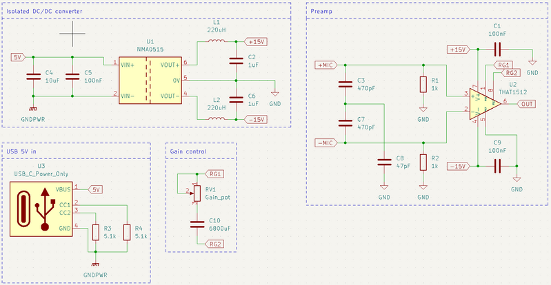
I've only started to look at this design a couple of days ago and I am by no means good enough at designing circuits myself to work on something as precise as the front end (analogue design is still incomprehensible wizardry to me), so I've been looking at the rest of the design instead. The use of 2200uF capacitors baffles me as they seem far too high of a value. I'm familiar with using a 100nF in combination with a 10uF capacitor on a USB power rail. Considering the USB 2.0 specification cites a maximum capacitance of 10uF, 2200uF seems like a VERY overkill design and might not be very friendly with something like a laptop USB 2.0 receptacle with the much larger inrush current. Next to that it forgoes the 100nF decoupling capacitors specified in the THAT1512 datasheet as well as the ripple reduction for the NMA0515. I've decided to just leave them out of the design, although I'm not certain if that is a good decision quite yet.
Following both datasheets, I end up with a design for the preamp that looks like this:
Apologies if it is somewhat difficult to read, I am not an expert on making legible circuits. I would love to combine this with the input stage you designed, however this preamp still relies on a differential signal so I'm not quite sure how to implement that with your input stage designs. This is also currently missing the audio coupling capacitors, of which I am thinking of using the ECW-FE2W225J 2.2uF PP-caps. (yes I insist on calling them PP-caps I'm a child at heart and still find it funny to say PP caps)
Is there something crucial I'm currently missing from this design, or something I've failed to notice about the original design? Do you see any improvements that can be made to this design, as someone who actually knows what he's doing?
Thanks for all your previous posts as well, they've been a delight to read! I've also already added The Art of Electronics to my Christmas list of "gifts I REALLY want".
Mine went bad too, I've got 50V non polar capacitor. Did you find any solution?Hi,
I managed to put everything together.
However, two of the 2200uF 16V capacitors went bad (the ones connected to the NMA0515SC). I checked for short circuits and there are none.
I was able to hear the microphone "working" but not properly, as there were loads of really loud humming and buzzing noises in the background (probably from the blown capacitors).
My components are basically the same as the ones used in the video except for the 22uF bipolar capacitors (mine are rated for 100V, in the video 35V). As their specification didn't include voltage ratings, I assumed it wasn't important.
Any ideas what may be causing the problem?

